control4.com | 888.400.4070
Connecting the contact port
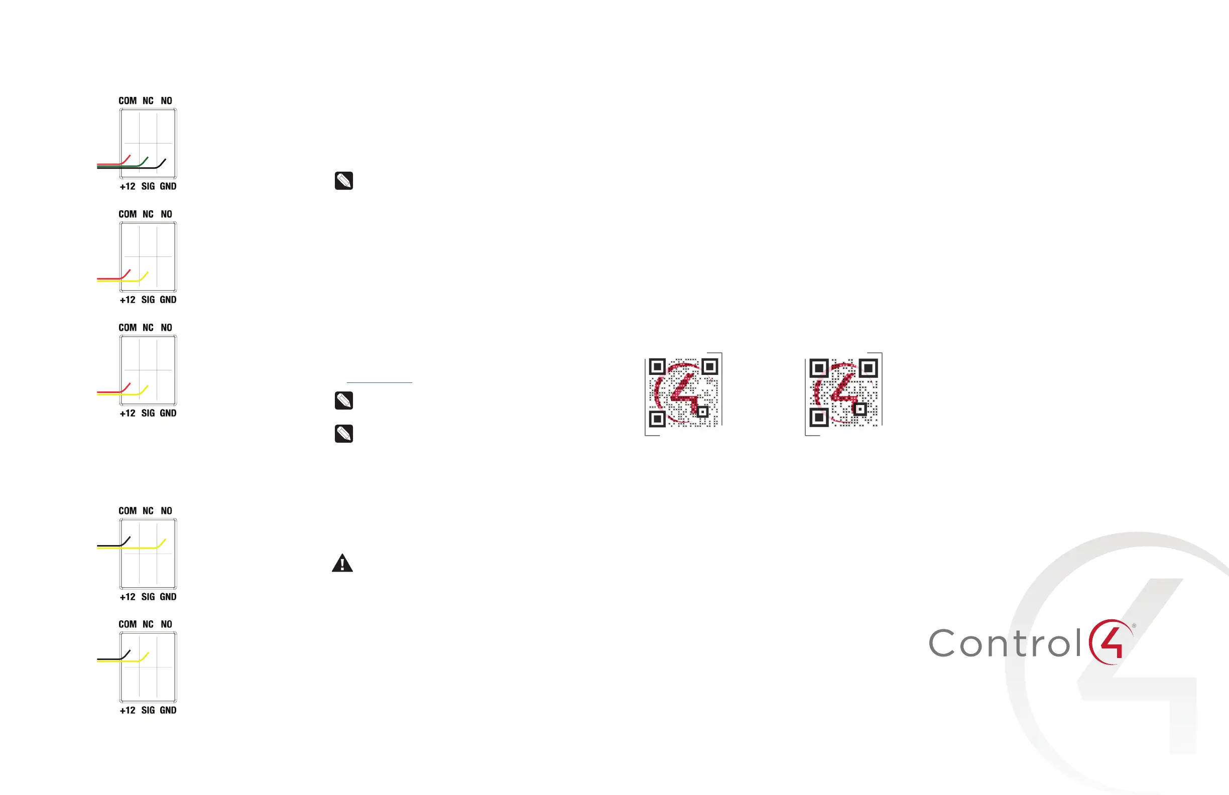
The EA-3 provides one contact port for the included pluggable terminal
block.
See Figures 3 through 5 to learn how to connect the device to the
contact port.
Figure 3. Contact Port for Voltage Source ( Motion Sensor)
Figure 4. Contact for Dry Contact ( Door Contact Sensor)
Figure 5. Contact for Self-Powered Voltage Source Device
Connecting the relay port
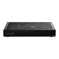
The EA-3 provides one relay port for the included pluggable terminal
block. With most applications, attach one wire to the COM terminal and
the other to the NO terminal. The relay switch closes when the relay is
activated.
Figure 7. Relay Port, Normally Open
Figure 8. Relay Port, Normally Closed
Connecting the IR ports/serial ports (optional)
The controller provides six IR ports. Ports 1, 2, and 3 can be
reconfigured independently for serial communication. If not used for
serial, they can be used for IR. Connect a serial device to the controller
using the Control4 3.5 mm-to-DB9 Serial Cable (C4-CBL3.5-DB9B, sold
separately).
1 The serial ports support many dierent baud rates (acceptable
range: 1200 to 115200 baud for odd and even parity). The serial
ports do not support hardware flow control.
2 See Knowledgebase article #268 (kb.control4.com/questions/268)
for pinout diagrams.
3 To configure a port for serial or IR, make the appropriate
connections in your project using Composer Pro. See the Composer
Pro User Guide for details.
Note: The serial ports can be configured as straight-through or
null with Composer Pro. Serial ports by default are configured
straight-through and can be changed in Composer by
selecting the option Enable Null-Modem Serial Port (1/2/3).
Set up IR emitters
Your system may contain third-party products that are controlled
through IR commands. The included IR emitters can send commands
from the controller to any IR-controlled device.
1 Connect one of the included IR emitters into an IR OUT port on the
controller.
2 Remove the adhesive backing from the emitter (round) end of the
IR emitter and ax it to the device to be controlled over the IR
receiver on the device.
Set up external storage devices
You can store and access media from an external storage device, for
example, a USB drive, by connecting the USB drive to the USB port and
configuring or scanning the media in Composer Pro. A NAS drive can
also be used as an external storage device, see the Composer Pro User
Guide (ctrl4.co/cpro-ug) for more details.
Note: We support only externally powered USB drives or solid-
state USB drives (USB thumb drives). USB hard drives that do
not have a separate power supply are not supported.
Note: When using USB storage devices on an EA-3 Controller,
you can use only one partition with a 2TB maximum size. USB
storage devices should be formatted FAT32. This limitation
also applies to USB storage on all other controllers.
Composer Pro driver information
Use Auto Discovery and SDDP to add the driver to the Composer
project. See the Composer Pro User Guide for details.
Troubleshooting
Reset to factory settings
Caution! The factory restore process will remove the
Composer project. Back up the project with Composer Pro
before you start the factory restore process
To restore the controller to the factory default image:
1 Insert a straightened paper clip into the small hole on the back of
the controller labeled FACTORY RESTORE.
2 Press and continue to hold the FACTORY RESTORE button, the
controller will reset and the caution LED will turn solid red.
3 Continue to hold the button for about five to seven seconds until
the caution LED blinks twice yellow. After the caution LED blinks
twice yellow, release the button and the factory restore process will
begin.
The caution LED will blink orange while the factory restore is
running. When complete, the caution LED turn os and the device
will reset.
Power cycle the controller
Press and hold the ID button for five seconds. The controller will reset.
Reset the network settings
To reset the controller network settings to the default:
1 Disconnect power to the controller.
2 While pressing and holding the ID button on the back of the
controller, reconnect power to the controller.
3 Hold the ID button until the data, link and power LEDs are solid
blue, then immediately release the button.
4 If the caution LED stays orange during the boot sequence, press
and hold the ID button until the caution LED blinks blue, and then
release it.
Regulatory/Safety information
To review regulatory information for your particular Control4 products,
see the information located on the Control4 website at
www.control4.
com/regulatory/
.
Warranty
Visit
www.control4.com/warranty
for details.
More help
For the latest version of this document and to view additional materials,
open the URL below or scan the QR code on a device that can view
PDFs.
MOST RECENT VERSION
ctrl4.co/ea3-ig
MORE INFO ON EA CONTROLLERS
ctrl4.co/
ea
200-00381-A
2015-07-06 DH
Copyright ©2015, Control4 Corporation. All rights reserved. Control4, the Control4 logo,
the 4-ball logo, 4Store, 4Sight, Control My Home, Everyday Easy, and Mockupancy are
registered trademarks or trademarks of Control4 Corporation in the United States and/
or other countries. All other names and brands may be claimed as the property of their
respective owners. All specifications subject to change without notice.
A