Primary Fan (Electric), Secondary Fan (Electric)
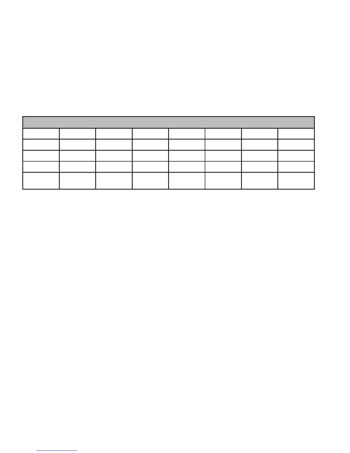
Stage Y1 Y2 W1 W2 O B G
1st Stage * * *
2nd Stage * * * *
3rd Stage * * * * *
E-Heat
(Stage 1)
* * *
• The Primary Fan switch selects the operating mode for auxiliary heat.
• The switch in the electric position indicates that the heat pump is connected to an air handler
system, and the Thermostat will control the ‘G’ fan relay. ‘Y1’ and ‘Y2’ will remain energized
during 3rd stage heating.
• The switch in the fuel position indicates the heat pump is connected to a furnace system
with the heat pump heat exchanger in-line (downstream) from the furnace hot air. In this
case, ‘Y1’ and ‘Y2’ will de-energize after a configurable auxiliary heat cuto delay and remain
de-energized during the remainder of the 3rd stage heat cycle.
• Emergency heat can only be activated by pressing the front panel control mode button.
Emergency heat is only available in a heat pump system, and will always activate relay ‘W2’
and de-energize ‘Y1’ and ‘Y2.’
• The Secondary Fan switch selects the operating mode for Emergency heat.
• The switch in the electric position causes the Thermostat to activate the ‘G’ fan relay.
20
 Loading...