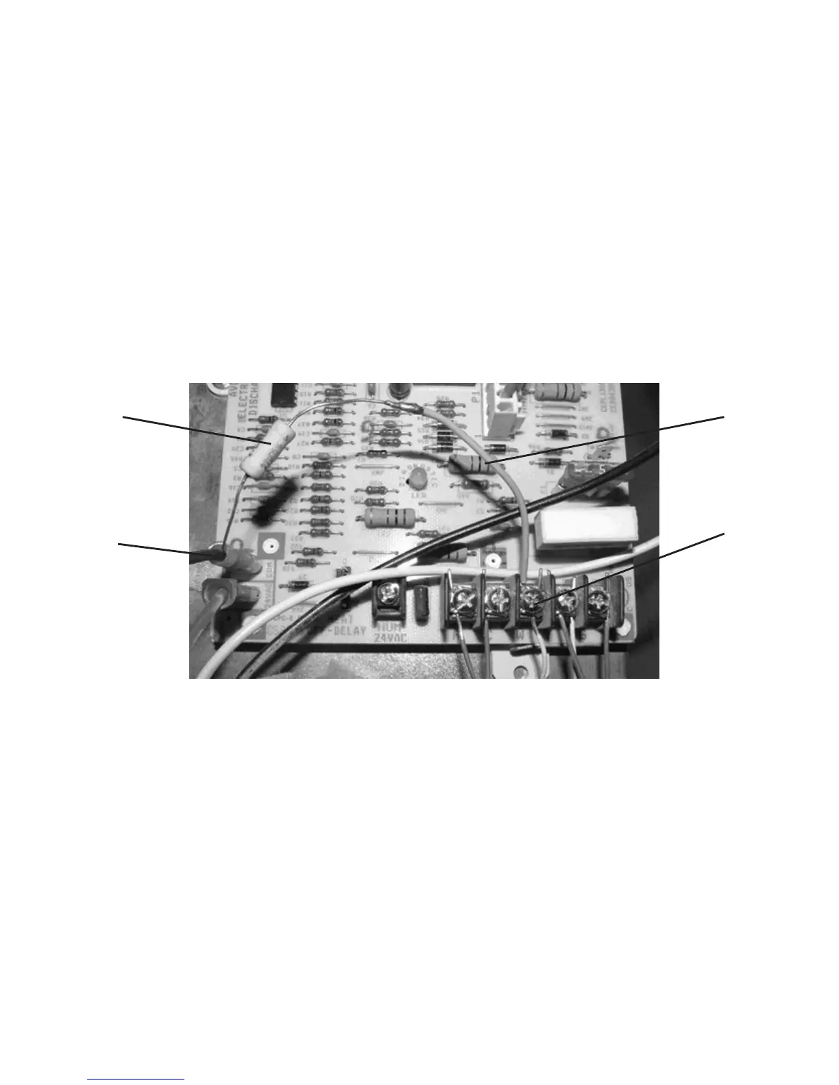
Example 2. This second example (Figure 9) shows a control board that does not provide a
common wire screw terminal. In this example, an additional length of wire was added to the
resistor which allowed it to connect from the ‘W’ terminal to the connector for the 24V com-
mon that connects from the HVAC transformer to the control board.
When the bypass resistor is in place, you should re-assemble any covers or housings that
were removed to access the transformer and control panel (often, safety switches prohibit
the HVAC equipment from running until all covers are in place).
Restore power to the HVAC system and test that both heating and cooling are functioning
correctly with the resistor in place.
6
7
27
Figure 9. HVAC without a Common Screw Terminal
Bypass Resistor
24V Common
Wire Extension
Heat Relay
Terminal (W)
 Loading...