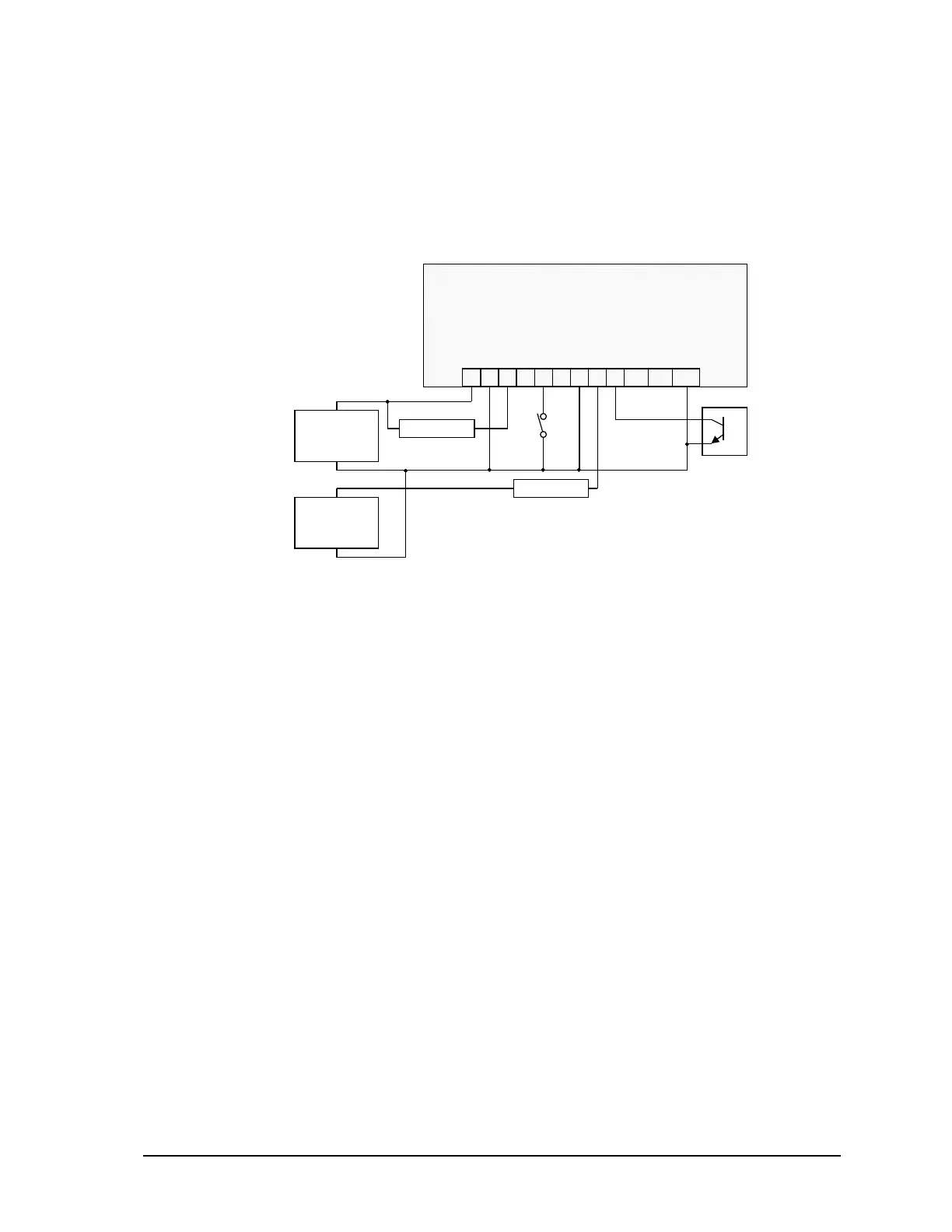
8.1 Digital I/O Connection Examples
Various I/O point wiring examples are shown in Figure 6: Digital Input/Output Wiring. Digital I/O
point 0 is shown connected to a 12V load that uses the same 12V power supply that powers the
SCADAPack 350. Digital I/O point 4 is shown connected to a 24V load and external 24V-power
supply. Digital I/O point 2 is shown monitoring a dry contact. Digital I/O point 5 is shown
monitoring an open collector contact. Transient voltage suppression is included on each I/O point.
109876543
GND0123 45
P3 – DC Power In and Digital I/O
+ 24V Load –
1 2
+–
11 12
67GND
+
12Vdc Power
Supply
_
+
24Vdc Power
Supply
_
+ 12V Load –
Figure 6: Digital Input/Output Wiring
SCADAPack 350 Hardware Manual
February 14, 2007
24