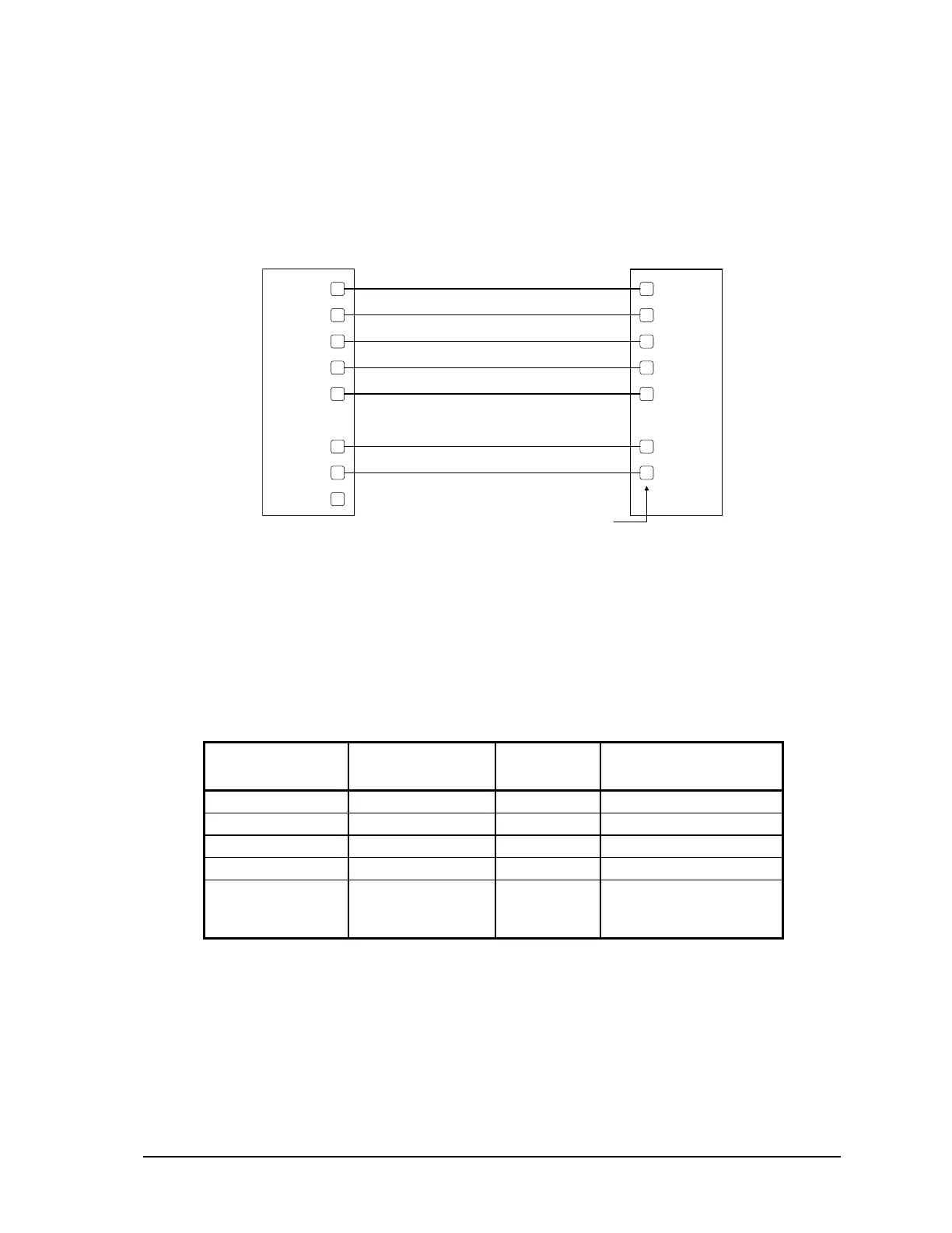
10.1.3.3 DTE to DCE with Handshaking
DCE devices require different wiring. The handshaking lines must be connected in most cases. Note
that many DCE devices are half-duplex. Select half-duplex operation with these devices. The
diagram below shows common connection of a SCADAPack 350 with a DCE device requiring
handshaking lines.
RS-232 COM port (DTE)
8 Pin connector
DCE
5
6
3
4
8
7
1
2
DCD
RxD
TxD
DT
GND
RT
CT
+5V
DCD
RxD
TxD
DTR
GND
RTS
CTS
See devi ce
specification
for pin number
Figure 16: RS-232 DTE to RS-232 DCE With Handshaking
10.1.4 RS-232 Cables
10.1.4.1 RJ-45 to DE-9S DTE
This cable is used to connect from an RJ-45 based RS-232 port on the SCADAPack 350 controller to
DE-9P connector on a DTE such as a PC. A 10 ft. long cable is available from Control Microsystems
as part number 297217.
RJ-45
8 Pins
SCADAPack
DTE Function
DE9S DTE
Function
DE9S
Shield connects to shell
6 TxD RxD 2
5 RxD TxD 3
4 GND GND 5
1, 2, 3, 7 and 8
are not connected
at this end.
Wires not connected at
this end.
10.1.4.2 RJ-45 to SCADAPack Vision
This cable is used to connect from COM3 (RJ-45 based RS-232) port on the SCADAPack 350
controller to DE-9P connector on a SCADAPack Vision. A 5-ft. long cable is available from Control
Microsystems as part number 297237.
SCADAPack 350 Hardware Manual
February 14, 2007
36