Status Relay 1 Normally open contacts
1 Dry contact output pole 1/2 5A, 240 VAC resistive
Drive OK (default)
2 Status Relay 1
Dry contact output pole 2/2
3 Circuit Common
0 VDC Analogue reference
4 +10 VDC ± 1% Voltage tolerance
User supply for external analogue signal device 10 mA output current (current limit protected)
5 Analogue Input 1 (non-inverting input) Bipolar ±10 VDC
Programmable Differential Analogue Input 100k½ input impedance
Analogue Speed Reference 1 (default) 12-bit plus sign resolution, ² 2mS sampling period OL
6 Analogue Input 1 (inverting input) <45 Oµs C.L.
Programmable Differential Analogue Input
7 Analogue Input 2 Programmable: ±10 VDC (default), 4-20mA,
Programmable Single-ended Analogue Input 20-4mA, 0-20mA inputs,
Analogue Speed Reference 2 (default) 100k½ input impedance
10-bit plus sign resolution
² 2mS sampling period
8 Motor Thermistor Input
Programmable Single-ended Analogue Input
9 Analogue Output 1 Programmable: ±10 VDC @ 10mA (max) (default)
Programmable Single-ended Analogue Output 4-20mA, or 0-20mA
Output Frequency (open loop default) 1k½ minimum load resistance
Speed Feedback (closed loop default) 10-bit plus sign resolution, 8mS update period
Short circuit protected
10 Analogue Output 2
Programmable Single-ended Analogue Output
Torque Output (default)
11 Circuit Common
0 VDC Analogue reference
21 OV Common
22 +24 VDC Voltage Tolerance: ±10%
User Supply Nominal Output: 200 mA
Overload Output: 240 mA with current foldback
protection
23 Circuit Common
0 VDC Digital reference
24 Programmable Logic I/O F1 Output Mode:
Output: At speed (open loop) User-defined: Negative or positive logic
At zero speed (closed loop) Negative logic (default)
Push-pull output, 0 - +24 VDC
100mA max output, 120mA overload current
Input Mode:
User-defined: Positive logic (V > +15 VDC)
or negative logic (V < +5 VDC) (default)
Voltage range: 0 - +24 VDC
3.2 mA max load at +24 VDC
25 Programmable Logic I/O F2
Input: Drive reset (default)
26 Programmable Logic I/O F3
Input: Jog (default)
27 Programmable Logic Input F4 User-defined: Positive logic (V > +15 VDC)
Latched Run Forward (default) or negative logic (V < +5 VDC) (default)
Voltage range:
0 - +24VDC, 3.2 mA max load @ +24 VDC
28 Programmable Logic Input F5
Latched Run Reverse (default)
29 Programmable Logic Input F6
Local (default)/Remote
30 Logic Input: Drive Enable (closed loop)
External Trip (open loop)
31 Circuit Common
0 VDC digital reference
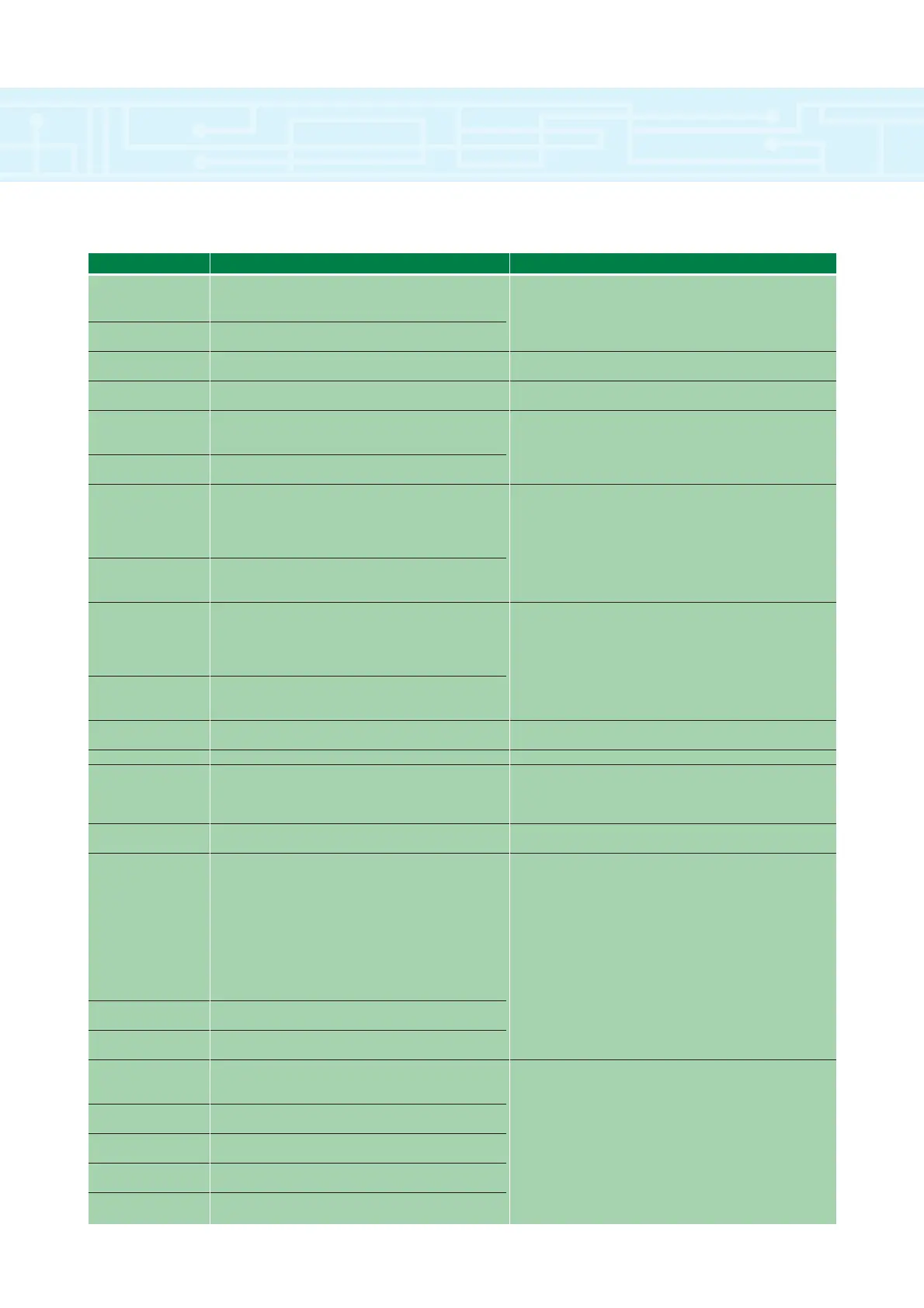
Control Inputs and Outputs
TERMINAL I/O TYPE & FUNCTION RATING
NOTE: There are no terminals numbered 12, 13...., 20 on the Unidrive
connections
16