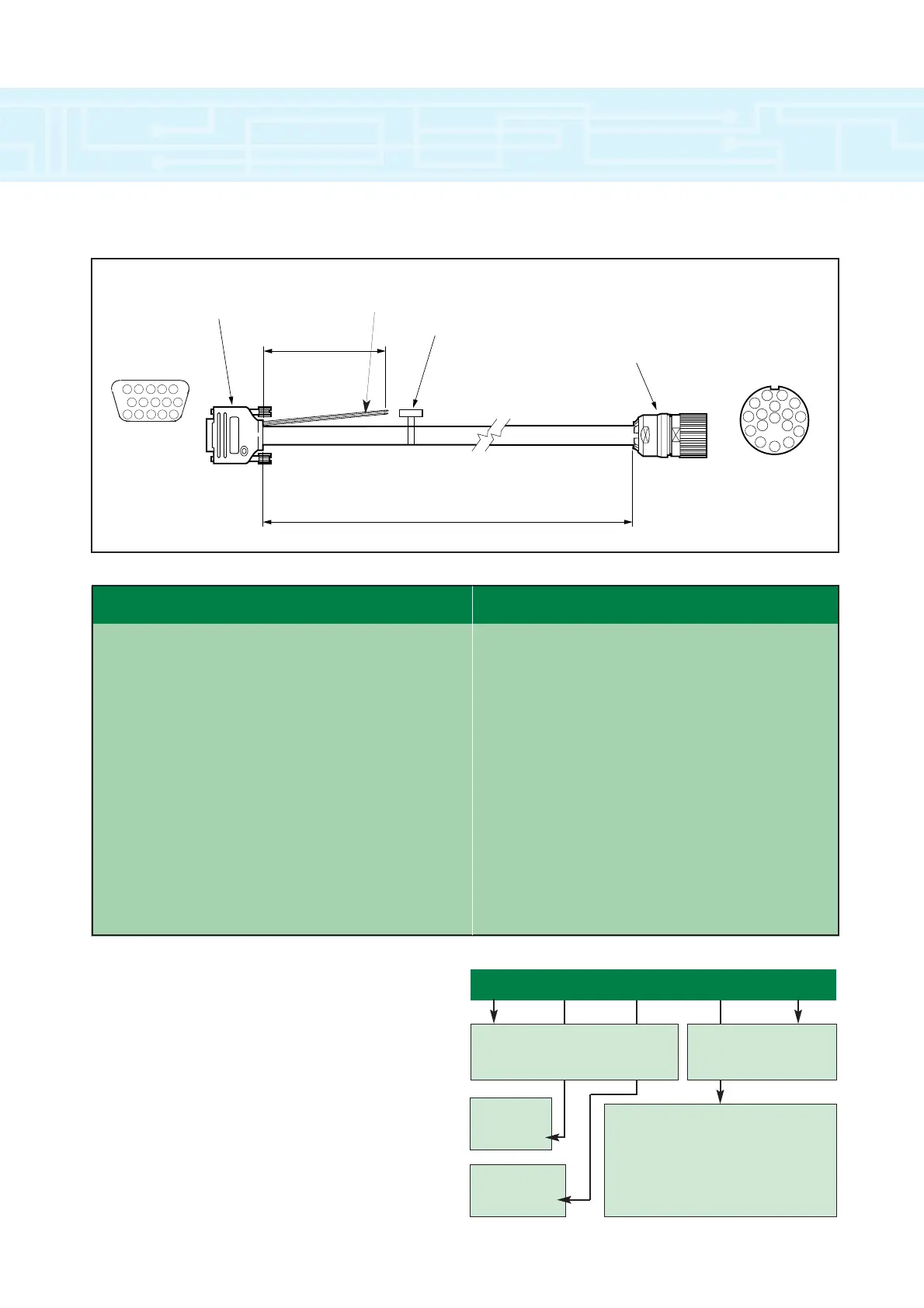
‘D’ Type Connector 17 pin Interconnectron Connector
Pin Colour Function Pin Colour Function
1 Grey/Pink Band Channel A 1 White Thermistor
2 Red/Blue Band Channel A Inverse 2 Brown Thermistor Rtn
3 Red (0.34mm
2
) Channel B 3 - Not Used
4 Blue (0.34mm
2
) Channel B Inverse 4 Green S1
5 White/Green Band Index 5 Yellow S1 Inverse
6 Brown/Green Band Index Inverse 6 Grey S2
7 Green S1 7 Pink S2 Inverse
8 Yellow S1 Inverse 8 Black S3
9 Grey S2 9 Purple S3 Inverse
10 Pink S2 Inverse 10 Grey/Pink Band Channel A
11 Black S3 11 White/Green Band Index
12 Purple S3 Inverse 12 Brown/Green Band Index Inverse
13 Red (1.0mm
2
) +5 Volts dc 13 Red/Blue Band Channel A Inverse
14 Blue (1.0mm
2
) 0 Volts 14 Red (0.34mm
2
) Channel B
15 - Not Used 15 Blue (0.34mm
2
) Channel B Inverse
- White Thermistor 16 Red (1.0mm
2
) +5 Volts dc
- Brown Thermistor Rtn 17 Blue (1.0mm
2
) 0 Volts
BODY Thermistor screen & overall screen BODY To overall screen
Thermistor Wire
Connections
5
5
5
5
5
5
5
5
5
5
5
4
3
2
1
10
1112
13
1415
9
8
7
6
Viewed from
rear
accessories
40
Ordering Information - Signal Cables
Use the information given on the following chart to
create an order code for signal cables. The top line is
a typical example.
Connector Type:
A - 15 Pin D type at Drive, 17 pin at Motor
B - Unfinished cut end at Drive, 17 pin at
Motor
C - Ferrule ends at Drive (for Small Options
Module), 12 pin at Motor for Resolver
X - Cable only
Special Options
A - Standard
A - 90
˚
elbow
Insulator:
A - PVC
B - PUR
SI B A A 095
Cable Type:
SI - Signal for Incremental Encoder
SR - Signal for Resolver Feedback
Cable Length (metres):
Min - 003 (3 metres)
Max - 100 (100 metres)