www.controltechniques.com4
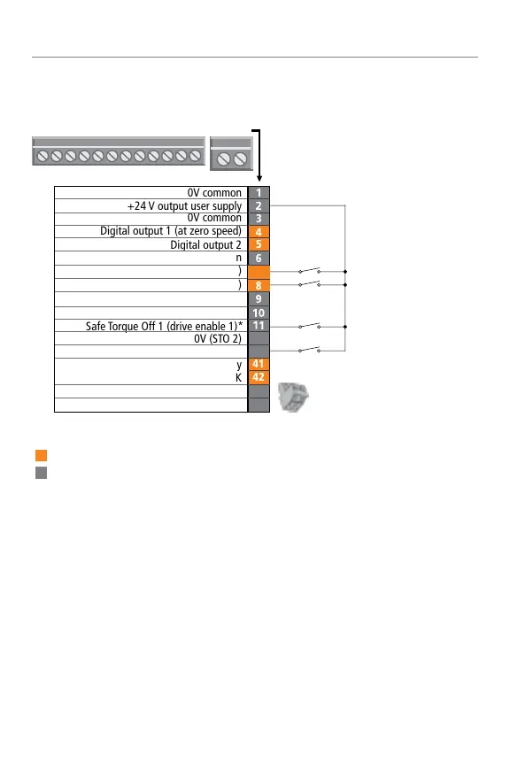
Control Wiring – Unidrive M702
The 0V terminals on the Safe Torque Off are
not isolated from each other and the 0V common.
* The Safe Torque Off / Drive enable terminal is
a positive logic only input.
†
Terminal 51 and 52 must be connected to an
external 24 V power supply if backup is required
(frame sizes 6-11E only).
Notes:
Programmable analog
Programmable digital
Non-programmable
• For frame size 5 to 9: STO input terminals
are 31 and 35; STO 0V terminals are 32 and 36.
* Terminal not available on frame size 1.
Notes:
Drive OK
Status relay
0V (STO 2)
Safe Torque Off 1 (drive enable 1)*
Digital output 2
Digital output 1 (at zero speed)
0V common
+24 V output user supply
0V common
52
51
42
41
8
7
6
5
3
Minimum connections to run motor
0V common
Digital input 4 (run forward)
Digital input 5 (run reverse)
12
13
Run FWD
Run REV
STO 1
STO 2
24 V
41 42
1
13
+24 V input external supply
Safe Torque Off 2 (drive enable 2)*
0V common external supply
†
+24 V external supply
†
Control connections
0V (STO 1)
* The Safe Torque Off/drive enable terminal is a positive logic only input.
† Terminal 51 and 52 must be connected to an external 24V power supply
if backup is required (frame sizes 6-11E only).