ISO 9001
(*) MVE contain a half-wave rectifi er power supply. They must not be powered with transformers that are used to power other
devices using not isolated full-wave rectifi er power supply.
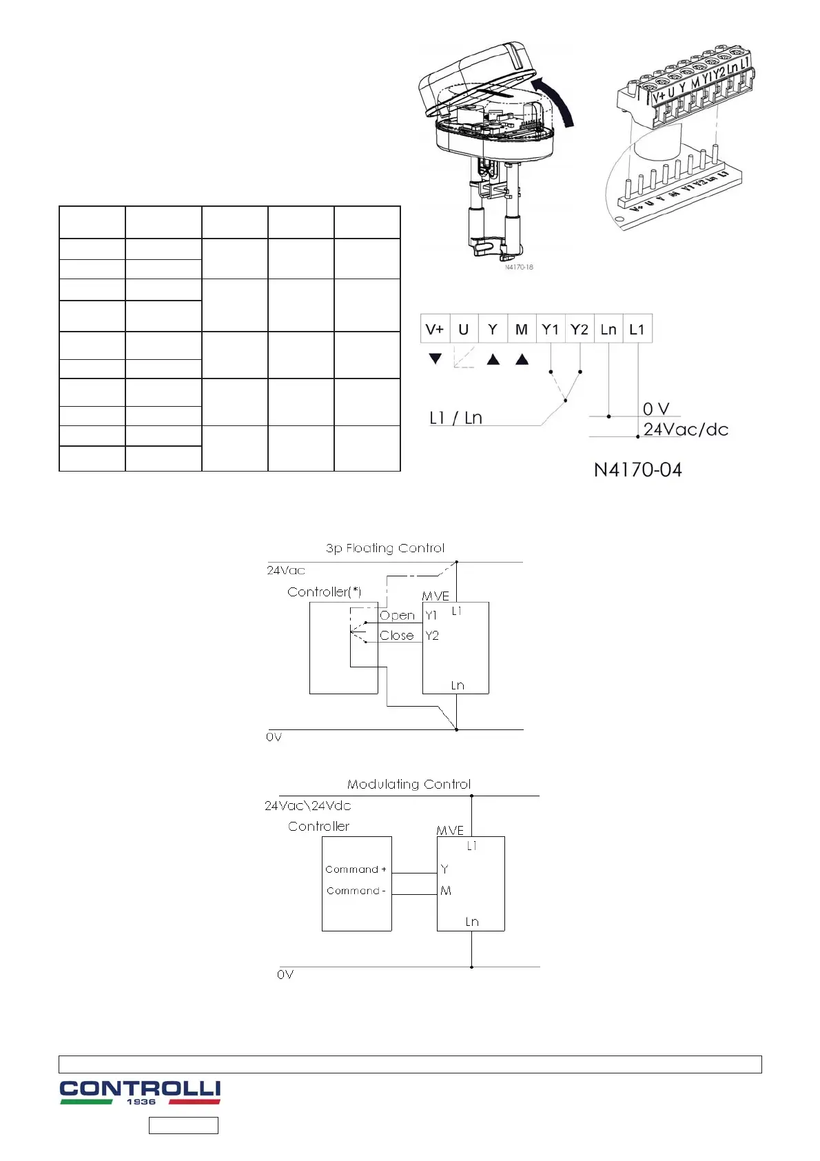
ELECTRIC CONNECTIONS
Remove the cover screw with a screwdriver and then remove
the cover as shown in the picture beside.
The actuator is equipped with a 8 poles removable terminal
block; the each pole of the plug is clearly marked and the same
label are reported on the PCB (Printed Circuit Board). Before
powering up the actuator make sure the plug is properly con-
nected to the PCB and the label on the plugs and on the PCB
match.
N4170-16
1st Issue rev. a 04/12 3 DBL388e
Label Description Function Min Wire
Size
Max wire
Length
L1 24Vac/Vdc
Power
Supply
1.5 mm
2
75 m
Ln 0 V
Y 0..10Vdc
Modulating
Control Input
0.5 mm
2
200 m
M 0 V (Common)
Y1 Open
Floating
Control Input
0.5 mm
2
200 m
Y2 Close
V+ 16 Vdc
Voltage
Output max
25mA
0.5 mm
2
200 m
M Common
U 2÷10 Vdc
Feedback
Output
Signal
0.5 mm
2
200 m
M 0V (Common)
TERMINAL BLOCK