2SQN IO&M B51141-004
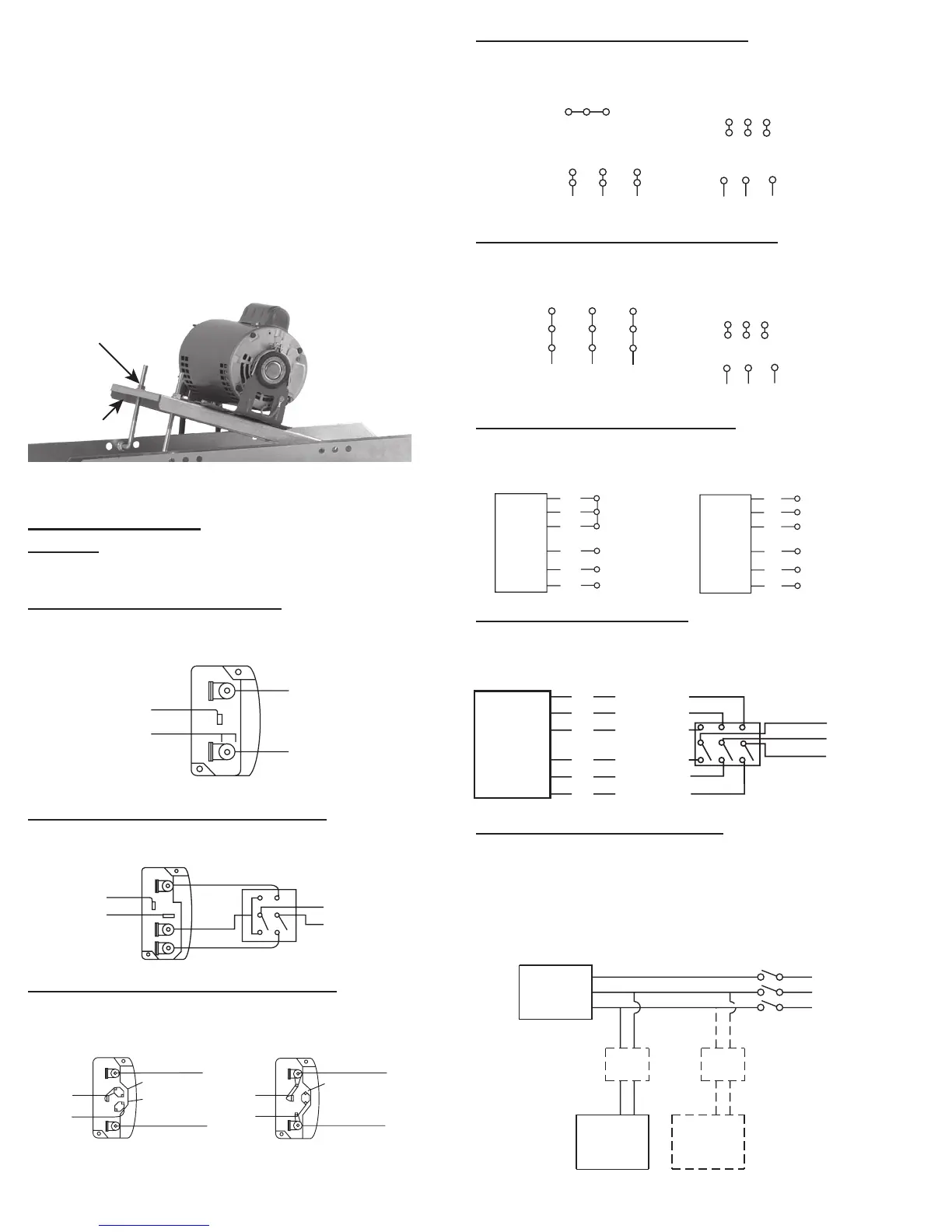
3 Phase, 9 Lead Motor Y-Connection
To reverse, interchange any 2 line leads.
4
5
6
1
7
2
8
3
9
456
7
8
9
12
3
208/230 Volts
460 Volts
3 Phase, 9 Lead Motor Delta-Connection
To reverse, interchange any 2 line leads.
7
1
6
789
4
5
6
12
3
08/230 Volts
460 Volts
8
2
4
9
3
5
L
1
L
3
L
2
2 Speed, 1 Winding, 3 Phase Motor
To reverse, interchange any 2 line leads. Motors require mag-
netic control.
Motor
1
2
3
4
5
6
Together
High Speed
Line
L
1
L
2
L
3
1
2
3
4
5
6
Open
Low Speed
L
1
L
2
L
3
Motor
2 Speed, 2 Winding, 3 Phase
To reverse: High Speed-interchange leads T11 and T12. Low
Speed-interchange leads T1 and T2. Both Speeds-interchange
any 2 line leads.
L
1
T
1
T
2
T
3
Low Speed
Low Speed
Low Speed
High Speed
High Speed
High Speed
Motor
T
13
T
12
T
11
L
2
Line
L
3
Typical Damper Motor Schematic
For 3 phase, damper motor voltage should be the same be-
tween L
1
and L
2
. For single phase application, disregard L
3
.
*Damper motors may be available in 115, 230 and 460 volt mod-
els. The damper motor nameplate voltage should be veried pri-
or to connection. **A transformer may be provided in some in-
stallations to correct the damper motor voltage to the specied
voltage.
Fan
Motor
Damper
Motor*
Second
Damper
Motor
Transformer**
Transformer**
L3
L2
L1
Storage
If the fan is stored for any length of time prior to installa-
tion, completely ll the bearings with grease or moisture-
inhibiting oil. Refer to Lubricants on page 5. Also, store the
fan in its original crate and protect it from dust, debris and
the weather.
To maintain good working condition of an SQN when it
is stored outdoors, or on a construction site, follow the ad-
ditional steps below:
• Cover the inlet and outlet, and belt tunnel opening to prevent
the accumulation of dirt and moisture in the housing.
• Periodically rotate the wheel and operate dampers (if supplied)
to keep a coating of grease on all internal bearing parts.
• Periodically inspect the unit to prevent damaging conditions.
e
djustment Nut
e
Adjustment
Wiring Diagrams
Vari-Flow
For EC or VF see EC Motor Wiring supplement. For VF2 see
PM wiring supplement.
Single Speed, Single Phase Motor
When ground is required, attach to ground A or B with no. 6
thread forming screw. To reverse, interchange T-1 and T-4.
T-1
4
L
2
L
1
Line
2 Speed, 2 Winding, Single Phase Motor
When ground required, attach to ground A or B with No. 6
thread forming screw. To reverse, interchange T-1 and T-4 leads.
T-1
4
Low Speed
High Speed
L
1
L
2
Line
Single Speed, Single Phase, Dual Voltage
When ground required, attach to ground A or B with No. 6
thread forming screw. To reverse, interchange T-5 and J-10
leads.
0
T-5
Link A
Link B
Low Voltage
Line
L
2
L
1
Link A & B
L
1
L
2
Lin
T-5
J-10
 Loading...