5
Replacing Pulleys and Belts
a. Clean the motor and fan shafts.
b. Loosen the motor plate mounting bolts to relieve the
belt tension. Remove the belt.
c. Loosen the pulley setscrews and remove the pulleys
from the shaft.
If excessive force is required to remove the pul-
leys, a three-jaw puller can be used. This tool,
however, can easily warp a pulley. If the puller is
used, inspect the trueness of the pulley after it is
removed from the shaft. The pulley will need
replacement if it is more than 0.020 inch out of
true.
d. Clean the bores of the pulleys and place a light coat of
oil on the bores.
e. Remove grease, rust and burrs from the pulleys.
f. Place fan pulley on the fan shaft and the motor pulley
on the motor shaft. Damage to the pulleys can occur
when excessive force is used in placing the pulleys on
their respective shafts.
g. After the pulleys have been correctly placed back onto
their shafts, tighten the pulley setscrews.
Belt and Pulley Installation
Belt tension is determined by the sound of the belts when
the fan is first started. The belts will produce a loud squeal,
which dissipates after the fan is operating at full capacity. If
belt tension is too tight or too loose, lost efficiency and
damage can occur.
Do not change the pulley pitch diameter to change tensi-
sion. The change will result in a different fan speed.
a. Loosen motor plate adjustment bolts and move motor
plate so that the belts easily slip into the grooves on
the pulleys. Never pry, roll, or force the belts over the
rim of the pulley.
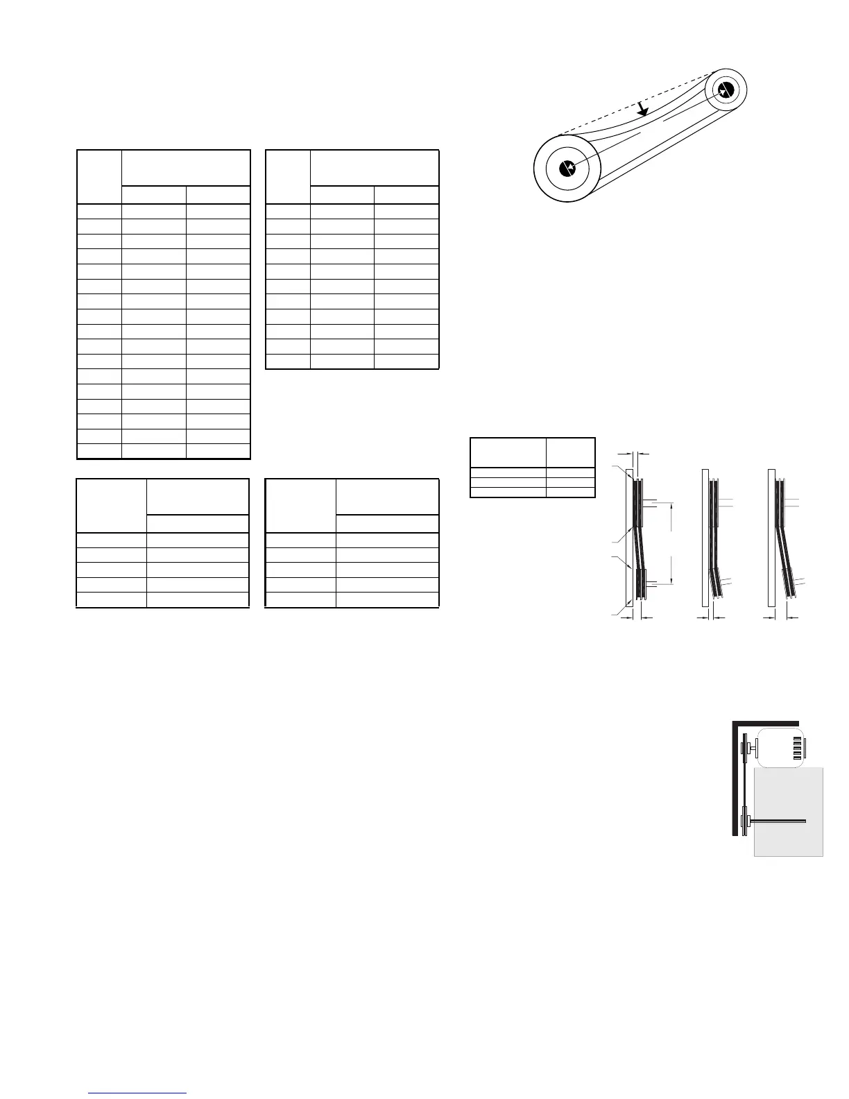
b. Slide the motor plate back until proper tension is
reached. For proper tension, a deflection of approxi-
mately 1/4” per foot of center distance should be
obtained by firmly pressing the belt. Refer to Figure 1.
c. Lock the motor plate adjustment bolts in place.
d. Ensure pulleys are properly aligned. Refer to Figure 2.
Pulley Alignment
Pulley alignment is adjusted by loosening the motor pul-
ley setscrew and by moving the motor pulley on the motor
shaft.
Figure 2 indicates where to measure the
allowable gap for the drive alignment toler-
ance. All contact points (indicated by
WXYZ) are to have a gap less than the tol-
erance shown in the table. When the pul-
leys are not the same width, the allowable
gap must be adjusted by half of the differ-
ence in width. Figure 3 illustrates using a
carpenter’s square to adjust the position of
the motor pulley until the belt is parallel to
the longer leg of the square.
Bearing Replacement
The fan bearings are pillow block type ball bearings.
a. Remove the old bearing.
b. Remove any burrs from the shaft by sanding.
c. Slide new bearings onto the shaft to the desired loca-
tion and loosely mount bearings onto the bearing sup-
port. Bearing bolts and setscrews should be loose
enough to allow shaft positioning.
Figure 1
OFFSET ANGULAR OFFSET/ANGULAR
A
W
X
Y
Z
B
CENTER
DISTANCE
(CD)
GAP
GAP
Figure 2
Tolerance
Center Distance
Maximum
Gap
Up thru 12” 1/16”
12” up through 48 1/8”
Over 48” 1/4”
Figure 3
Maximum RPM
VCR
Size
Maximum RPM
VCR-HP
Size
Maximum RPM
Standard Reinforced Standard Reinforced
100 2002 - 150 1952 -
120 1671 - 165 1728 -
135 1574 - 180 1829 -
150 1520 - 195 1570 -
165 1295 - 210 1626 -
180 1546 - 225 1435 -
195 1353 - 245 1185 1234
210 1227 - 270 1025 1049
225 1086 - 300 980 1046
245 901 - 330 830 912
270 766 - 365 735 872
300 837 877
330 716 748
365 624 659
402 539 560
445 463 473
490 360 403
Maximum RPM
VCR-XP
Size
Maximum RPM
VCR-XP
Size
Maximum RPM
Standard Standard
165 2508 245 1616
180 2396 270 1656
195 2100 300 1391
210 2126 330 1182
225 1879 365 1132
 Loading...