EXT-0087-R00-01082020 (LTR) 11/17
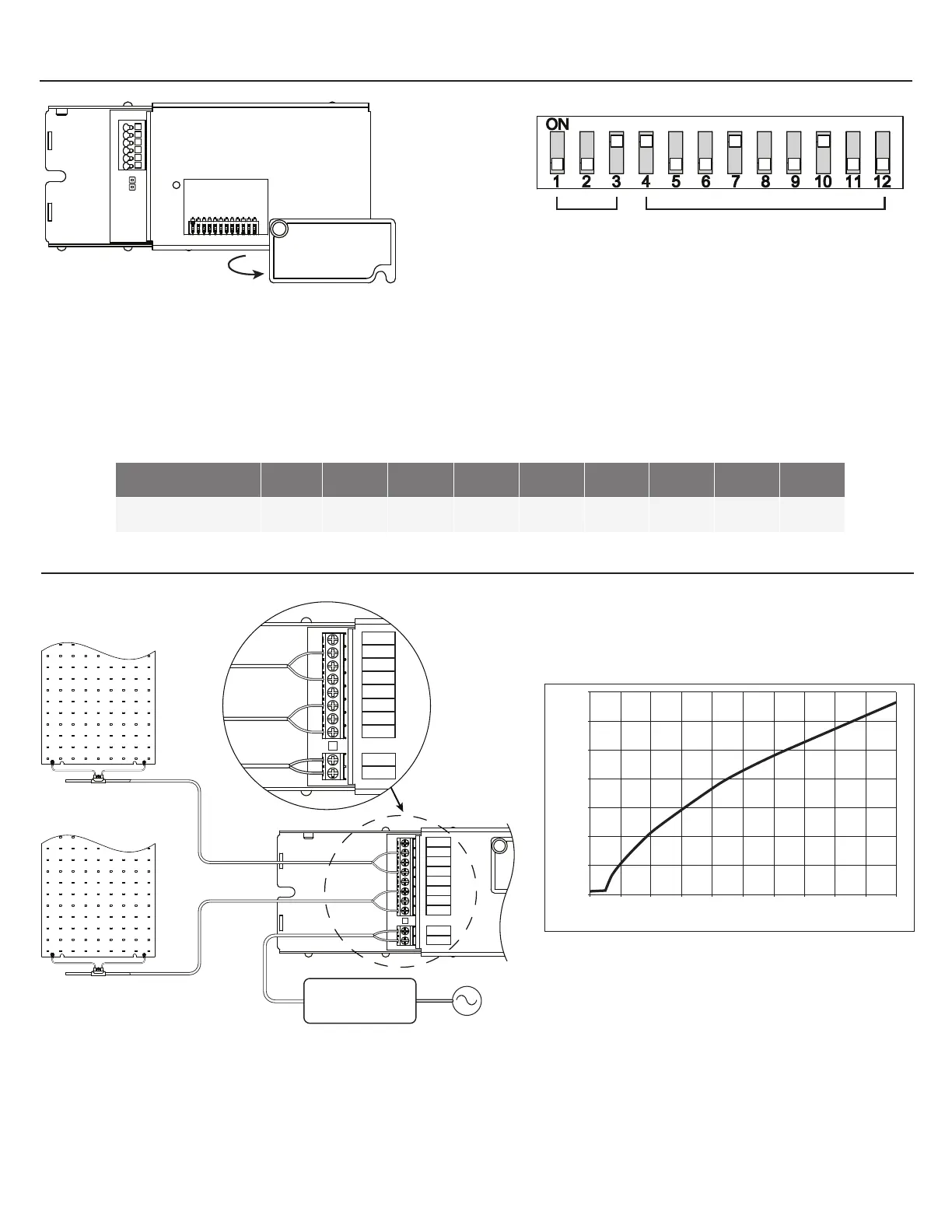
- To access the dip switch for selecting addresses for DMX controls, unfasten the cover screw and rotate cover out of the way.
DMX Controllers are factory set to address 1
- Each of the 9 switches (4-12) represents a bit in binary representation for the address. For example, when switch 12 is ‘ON’ only
address 1 is selected, if switch 12 & 11 are ‘ON’ then address 3 is selected. The address is selected by the sum of the values of
each ‘ON’ switch. Addresses 1 through 511 are possible
Switch: 4 5 6 7 8 9 10 11 12
Address: 256 128 64 32 16 8 4 2 1
SELECTING DMX ADDRESSES
- Switches 1 - 3: Factory set, refer to EXT-0071 for details.
- Switches 4 - 12: Addressing switches.
1 = On , 0 = O
DMX
3600
3400
3200
3000
2800
2600
2400
2200
0% 10% 20% 30% 40% 50% 60% 70% 80% 90% 100%
Dim Level
CCT (K)
CH 1+
CH 1-
CH 2+
CH 2-
CH 3+
CH 4+
CH 3-
CH 4-
+VIN
GND
RED OR WHITE
BLACK
RED OR WHITE
BLACK
CH 3+
CH 4+
CH 3-
CH 4-
OUTPUTS
CH 1 & 2: 90W
PSU 58V
100/200W
CH 3 & 4: 90W
Figure 1: Dim Inputs vs CCT Output
CH 3 & 4
CH 1 & 2