EXT-0087-R00-01082020 (LTR) 8/17
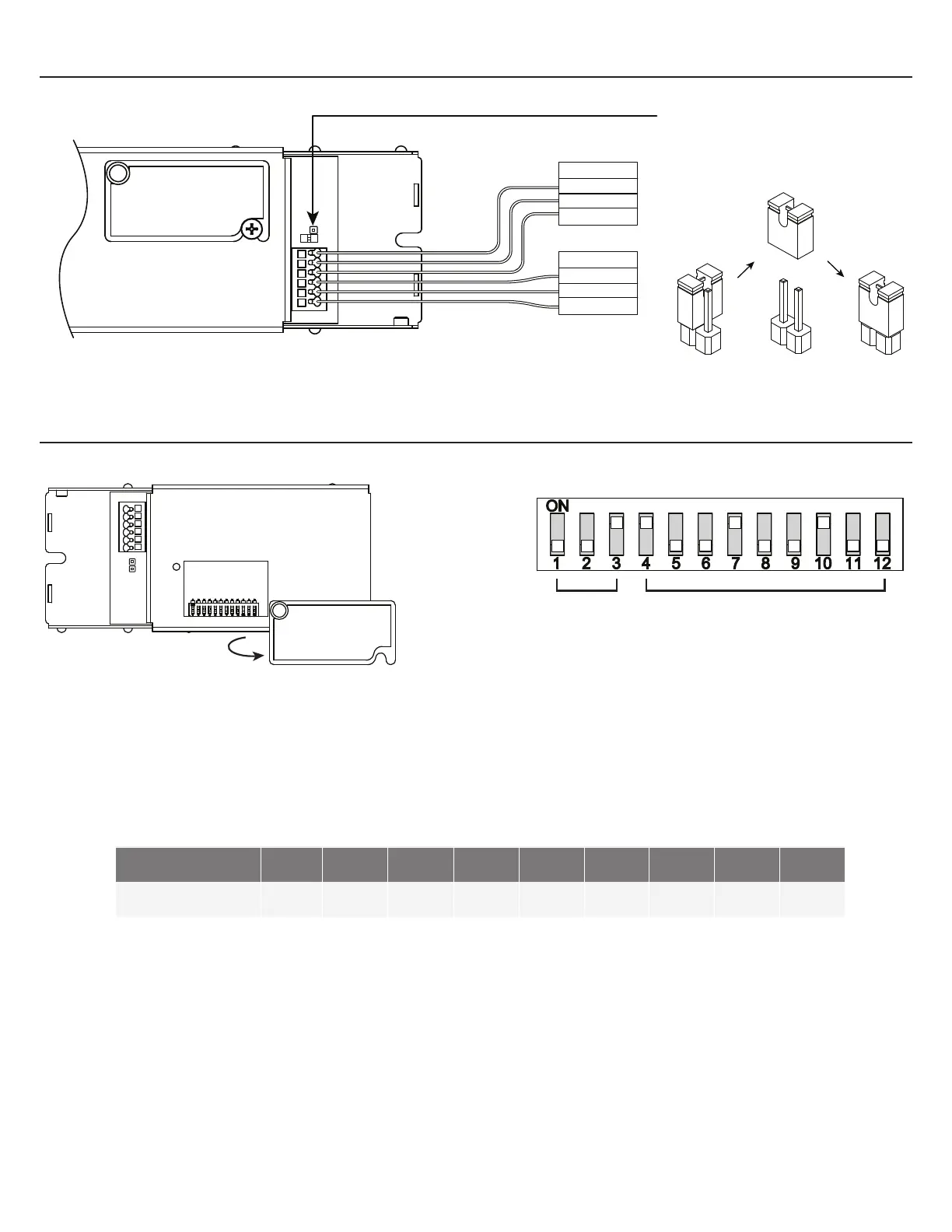
CONTROL INPUTS: DMX
DMX OUTPUT
GND
D-
D+
DMX INPUT
GND
D-
D+
When installing the final controller (termination
point) in a DMX network use the provided jumper
on the indicated header.
- To access the dip switch for selecting addresses for DMX controls, unfasten the cover screw and rotate cover out of the way.
DMX Controllers are factory set to address 1
- Each of the 9 switches (4-12) represents a bit in binary representation for the address. For example, when switch 12 is ‘ON’
only address 1 is selected, if switch 12 & 11 are ‘ON’ then address 3 is selected. The address is selected by the sum of the
values of each ‘ON’ switch. Addresses 1 through 511 are possible
Switch: 4 5 6 7 8 9 10 11 12
Address: 256 128 64 32 16 8 4 2 1
SELECTING DMX ADDRESSES
- Switches 1 - 3: Factory set, refer to EXT-0071 for details.
- Switches 4 - 12: Addressing switches.
1 = On , 0 = O
DMX
DMX