EasyManua.ls Logo

Cooper safety CF3000 - User Manual

Cooper safety CF3000
42 pages
Print Icon
To Next Page IconTo Next Page
Loading...
CF3000 / DF6000 FX6000
Application Guide
Fire
The large capacity, ability to support complex cause and
effect programming and wide range of user-controllable
functions make these panels suitable for a wide range of
projects from sheltered housing to large office
developments as well as many industrial applications.
This range of panels provide a large (120mm x 90mm) touch
screen display as the main user element, eliminating the need
for dedicated system push buttons. The user interface is
menu-driven, automatically reconfiguring to suit the chosen
menu option. To enable text updates directly at the panel, the
display converts to a full QWERTY keyboard, enabling
comprehensive text insertion.
The panels also have 96 zone fire LEDs providing additional
information about the extent of any fire activation as well as a
comprehensive set of system status LEDs providing
additional visual information for the end user.
The panels use ‘spur tolerant’ soft addressing to minimise
installation time and remove the potential for error normally
associated with manual addressing.
Benefits and Features
> LPCB 3rd party approved to latest: EN54-2 1997,
A1: 2006 EN54-4 1997, A1: 2002 and A2: 2006
> VdS, BOSEC, CNBOP Certified
> Choice of 1, 2 and 4-loop panel options
> Large multi functional touch screen
> Spur tolerant soft addressing
> Short circuit isolators incorporated into each loop
device
> Up to 200 addresses per loop
> Fully monitored network capable up to 127 panels
> Optional integral printer
Question and Answer IconNeed help?

Do you have a question about the Cooper safety CF3000 and is the answer not in the manual?

Summary

Benefits and Features

Recent Amendments

Menu Structure

User Access Code

Explains access levels for panel operation and configuration.

Engineers Menu

Describes the dedicated menu for technical engineers and system setup.

Zones

Access Codes

Disable;Enable Devices

Replace Device

Check Auto Config

Delays

Double Knock

Coincidence (Dependency type C)

Weekly Test

Sounder Level Test

One Man Walk Test

Test Device

Disable All Outputs

Auto Learn

Analogue Level

Printer Settings

Programming I;O and Sounders & Sub-Menus

Panel Outputs

Details programming options for sounder tone and volume for loop-powered devices.

T1 & T2

Alarm Verification Feature

Auxiliary Board

HMO Mode

Sounder Tone

Double Knock Override

Change Text

Input Programming

Output Programming

Add;Delete

Configure Heat Detectors

Network programming

Day; Night Settings

High Level Menu

Disable all Outputs

Enables engineers to test the system without activating any outputs.

Buzzer Disabled;Enabled

Allows permanent disabling of the panel's buzzer with a visual indicator.

Intermittent Fault Search

Feature to quickly identify intermittent faults by forcing immediate indication.

Logos

Allows engineers to change the logo displayed on the panel's front screen.

Reset to Factory Settings

Restores the panel to its default factory settings, erasing all programming.

Fire Routing & Protection Equipt

Enables setting delays for Fire Routing and Protection Equipment outputs.

Sounder 1 & Sounder 2

Configures conventional sounder circuits for continuous, pulsing, or delayed operation.

Terminology

Autolearn Locking

Evacuate Locking

Australian FB Screen

UL 864 9 th Edition

Networking

1. Introduction

Overview of networking capabilities, panel limits, and technology used.

2. Cable Types

Specifies recommended cable types and installation guidelines for network connections.

3. Configurations

Ancillary Devices

1. Detection

Covers different types of detectors like Photoelectric, Ionisation, and OptoThermal.

2. Callpoints

Describes the types and functionalities of manual call points.

3. Sounders

Explains the programming and limitations for sounder and beacon devices.

4. Input;Output Devices

5. Zone Monitoring Units

6. Fan Controller FC6

7. 4 Way Sounder Control Unit (MPU 424)

8. MARDF6

9. Spur Isolator- MS1850

10. Beam Detector MAB50;100 R

11. Repeaters

Getting Started & Fault Diagnosis

Powering the panel

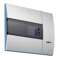
Guides on powering up the panel and initial boot sequence checks.

Power LED not illuminated

Troubleshooting steps for when the panel's power LED is not lit.

Power LED on but touch screen is not illuminated

Steps to diagnose issues when the power LED is on but the screen is blank.

Commissioning

1. Loop Checking with a multimeter

Detailed procedure for checking loop continuity and voltage using a multimeter.

2. Auto-Learn Function

Step-by-step guide for the auto-learn process to configure devices.

Faults and Solutions

1. Dual address

Describes the fault when two or more addresses respond simultaneously and its causes.

Open circuit Positive;Negative

Short Circuit start or end of a loop

Short circuit middle

Fault at address

Earth Fault

Sounder 1 or 2 Fault

FRE, FPE, Fault relay Fault

The panel goes into fire straight after auto-learn

The panel constantly resets after auto-learn

The panel fails to auto-learn past a device

Locating a fault on a loop

Other Faults

1. Charger Fault

Diagnoses issues related to the panel's battery charger system.

2. Battery Fault

Addresses problems with the panel's battery performance or voltage.

3. Mains Fault

Troubleshoots issues related to the loss of mains power supply.

4. Error Codes

Programming Issues

Program Updates

1. Loop Driver

Instructions for updating the software of the loop driver modules.

2. Display

Procedures for updating the panel's display software using utility programs.

Panel Comm

Download Analogue levels and Log to PC

CF3000; DF6000; FX6000 MOTHERBOARD

Cooper safety CF3000 Specifications

General IconGeneral
BrandCooper safety
ModelCF3000
CategoryControl Panel
LanguageEnglish