Page 8
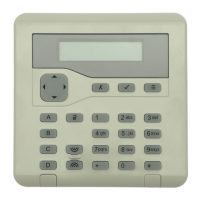
KEY-KP01
Installation
Siting the Keypad
Do site the keypad:
Within the area protected by the alarm system.
At a convenient height and location for the user.
Out of sight of potential intruders.
Do NOT site the keypad:
Next to electronic equipment, particularly computers, photocopiers or other
radio equipment, CAT 5 data lines or industrial mains equipment.
Where the cable run from the end station will be longer than 100m
to an i-on16, 250m to an i-on40 or 1,000m to an i-on50EX/160EX/
Menvier30/40/100/300.
Note: Do not site two or more keypads, or a keypad and an external prox
reader, closer than one metre together. Otherwise their prox readers will inter-
fere and be unable to read tags. For the same reason do not place the keypad
or external prox reader less that one metre from any other type of proximity
tag reader, for example those used in access control systems.
Fitting
Use 4mm x 25mm countersunk screws with a thread suitable for the wall ma-
terial. Fit in at least three xing holes when mounting the back of the keypad
on the wall. (See Figure 4.) A screw is supplied for the tamper block.
Cooper Security recommend that you mount the keypad as follows:
1. Select which cable entry you are going to use and break out the appropriate
plastic sections.
2. For Security Grade 3 installations:
a) Hold the backplate in place against the wall and mark the position of the
hole in the tamper block (see Figure 3).
b) Drill and plug the hole, and screw the backplate to the wall through the
tamper block using the supplied screw. Do not tighten the screw com-
pletely home.
3. Make sure the backplate is level and mark, drill and plug at least three other
xing holes. Screw the backplate to the wall through the xing holes using
the M4 screws.
4. For Security Grade 3 installations cut the plastic webs connecting the
tamper block to the remainder of the baseplate.
Note: If you do not cut the webs then the tamper switch will not operate if the
complete keypad is forced off the wall. The keypad will not comply with Grade
3 requirements.
5. Mount the front of the keypad (containing the keypad pcb) onto the back-
plate and make sure that the tamper switch operates.
Connect Keypad to End Station
CAUTION: Remove all power (both mains and battery) from the control unit
before connecting the keypad. Figure 7 shows connection details.