QD3 Quik-Drive Voltage Regulator Tap-Changer Manual
24
Main Moveable Contact Removal
and Re-assembly
Removing Main Moveable and Geneva Assembly
1. Use a 9/16 wrench or a deep well 9/16 socket and
ratchet, loosen and remove the number one main
stationary contact stud mounting nut, lock washer,
and flat washer. (See Figure 51.)
2. Remove stationary contact one from the contact
assembly board. (See Figure 52.)
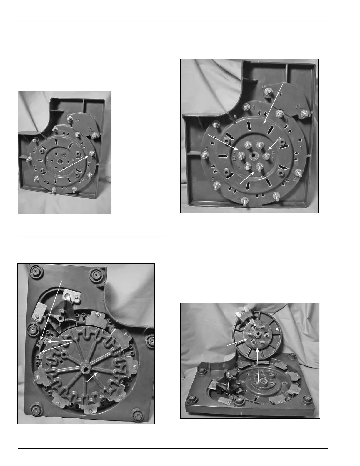
Figure 51.
Removal of stationary contact.
Stationary One Contact
Figure 52.
Moveable contacts.
Moveable Contact Assembly
Stationary Contact One
Position
Moveable Contacts
3. By hand, rotate the main moveable contact and
Geneva gear assembly so that the moveable contact is
in the stationary one contact position. (See Figure53.)
4. Use a 9/16 wrench or deep well 9/16 socket and
ratchet to remove the six nuts, lock washer, and flat
washer fastening the P1 and P2 slip ring studs to
the contact panel located in the center back of the
stationary contact panel. (See Figure 53.)
5. Facing the Main moveable contact and Geneva gear
assembly, pull forward removing the main contact
assembly and P1 and P2 slip ring assemblies for the
contact board assembly. (See Figure 54.)
Figure 53.
P1 and P2 connections.
P2 Connection
Contact Panel
P1 Connection
Six P1 & P2 Connection Studs
Figure 54.
Moveable contact dis-assembly.
Moveable
Contact
Assembly
P1 & P2 Studs
Slip Rings