QD3 Quik-Drive Voltage Regulator Tap-Changer Manual
26
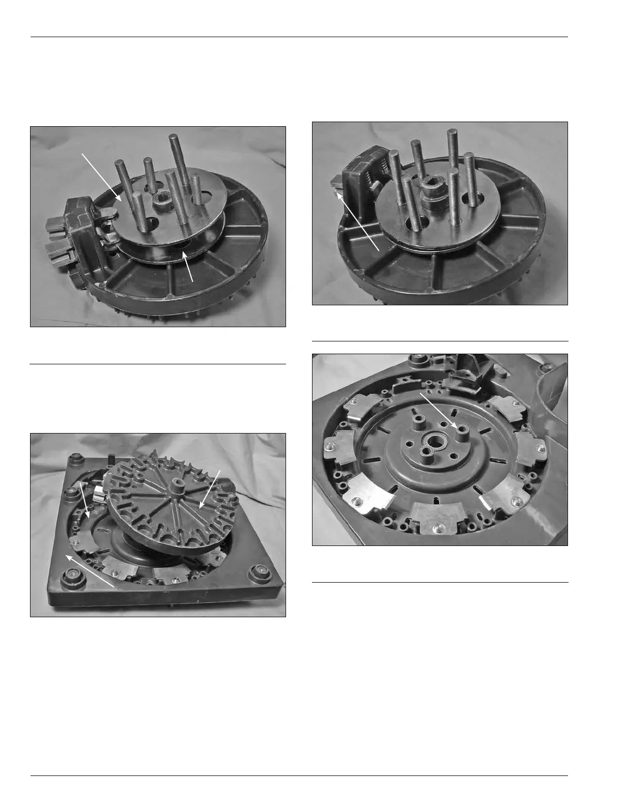
8. Place the second slip ring stud assembly over the first
ring assembly studs and the Geneva hub. Angle the
ring assembly so that the ring can be inserted between
the button contacts on the right hand upper moveable
contact. (See Figure 59.)
9. Align the moveable contact and Geneva gear assembly
so that the moveable contacts align up where the
number one stationary contact has been removed.
(See Figure 60.)
Figure 59.
Slip ring and moveable contact assembly.
Second Slip Ring
First Slip Ring
Figure 60.
Contact panel and moveable contact assembly.
Stationary Contact One
Position
Stationary Contact Assembly
Moveable Contact
Assembly
10. Align the stud of the slip rings with the mounting holes
in the contact panel. The studs on the slip ring that
is between the left hand lower button contact (Figure
61) will go into the holes that have the higher shoulder
spacer as part of the contact panel. (See Figure 62.)
11. You may need to rotate the slip ring assemblies in the
bottom contact to make the proper alignment.
12. Press the moveable and Geneva contact assembly to
insert the studs.
13. You may find that after starting the studs the moveable
and Geneva contact assembly will need to be rotated
to position the moveable contact so that the contacts
are not interfering with other stationary contacts
during the installation.
Figure 61.
Stud positioning.
Left Hand Button Contact
Figure 62.
Raised shoulder mounting.
Raised Shoulder Mounting Holes
for Slip Rings