S225-12-1
35
!
SAFETY
FOR LIFE
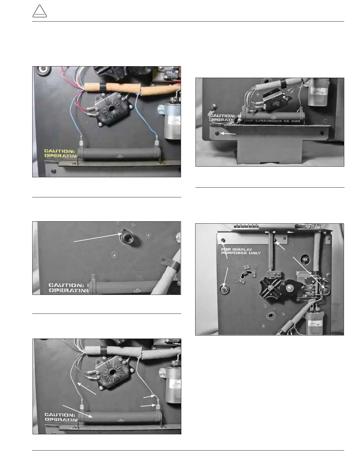
2. Use a Phillips head screwdriver to loosen and remove
the three mounting screws fastening the position indi-
cator micro switch hub to the front of the tapchanger
assembly. (See Figure 88.)
3. Remove the tapping indicator position lob pointer from
the tapchanger. The lob may have to be pried a little to
be removed. (See Figure 89.)
Indicator Position Lob
4. Disconnect and remove the blue and red strip leads from
the 40ohm resistor. These connections are pushon
connection. (See Figure 90.)
Bracket Fasten Screws
Figure 90.
40 Ohm resistor connections.
40Ohm Resistor
Blue/Red Leads
7. Using a 5/32 Allen wrench loosen and remove the pan
head Allen screws fastening the front drive assembly
section and the contact panel assembly section togeth-
er. (See Figure 92.)
Screws
Screws
Figure 92.
Driver panel and contact panel fastening.
Figure 91.
Tap-changer bracket mounting.
5. Lay the tapchanger assembly at on a work surface
with the tap contact studs down on the surface.
6. Use a 5/32 Allen wrench to loosen and remove the two
pan head Allen screws from the tapchangermounting
bracket. (See Figure 91.)
Figure 88.
Position indicator hub.
Figure 89.
Indicator position lob.
Screws
Position Indicator Hub