S225-12-1
53
!
SAFETY
FOR LIFE
5. Use a Phillips head screwdriver and needle nose pliers
to disconnect the white E control winding leads, and P
leads if available, from the seven position terminal board
located on the left top of the tapchanger. (See Figure
151.)
Control winding E lead and (P lead if available) Connections.
The E lead will have E lead ID markers and the P leads if avail-
able will have P lead markers.
TABLE 18
Lead Marker and Terminal Board ID
Lead Marker Terminal Board ID
E Could be on either E1, E2, or E3
E1 E1
E2 E2
E3 E3
P If available could be on either P1, P2, or
P3
P1 P1
P2 P2
P3 P3
Figure 151.
E & P lead connections.
E3
E2
E1
G
CAUTION:
Do not remove lead ties from lead bundles hold-
ing the tap leads in a certain position. Try to keep
from moving the lead bundles from normal position.
Doing so can result, possibly, in de-electric failures.
6. Use a deep well 9/16 inch socket with ratchet or a 9/16
inch wrench to loosen and remove all lead connections
from the back of the tapchanger contact board. (See
Figure 152.)
Figure 152.
Tap leads and reactor connections.
Tap Lead Connections
Reactor P1 & P2
Connections
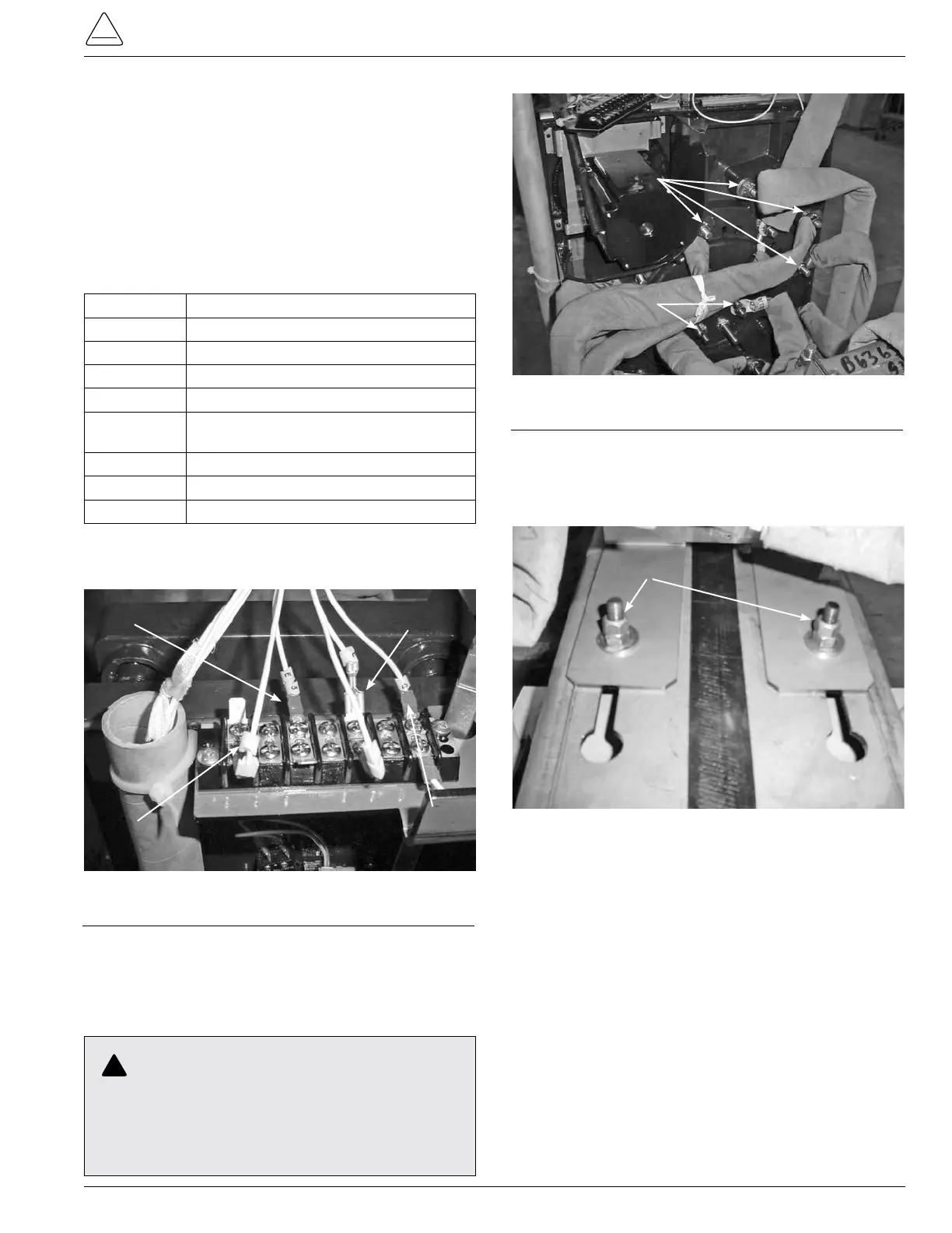
7. Remove the mounting bolts fastening the tapchanger
mounting bracket to the top core clamp. (See Figure
153.) Remove the tapchanger from the regulator and
place on a work surface.
Mounting Hardware
Figure 153.
Tap-changer to core clamp fastening hardware.