QD3 Quik-Drive Voltage Regulator Tap-Changer Manual
54
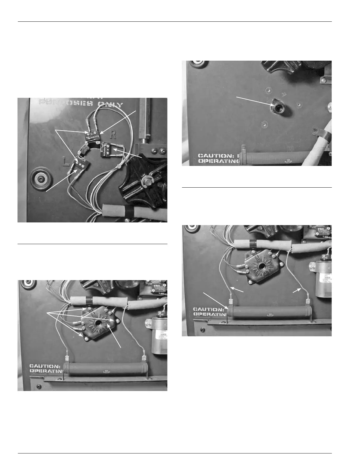
QD3/T350 Tap-Changer Assembly
Separation
1. After removing the tapchanger from the regulator
assembly, use a Phillips one point screwdriver to loos-
en and remove the six screws mounting the Reversing
Lower, Raise and Neutral switch located in the upper left
corner of the tapchanger assembly. (See Figure 154.)
Figure 154.
Lower, raise and neutral logic switches.
Screws
Lower
Raise
Neutral
2. Use a Phillips head screwdriver to loosen and remove
the three mounting screws fastening the position indi-
cator micro switch hub to the front of the tapchanger
assembly. (See Figure 155.)
Figure 155.
Position indicator hub.
Position
Indicator
Screws
3. Remove the tapping indicator position lob pointer from
the tapchanger. The lob may have to be pried a little to
be removed. (See Figure 156.)
Figure 156.
Indicator position lob.
Indicator
Position
4. Disconnect and remove the blue and red strip leads
from the 40ohm resistor. These connections are push
on connection. (See Figure 157.)
Figure 157.
40 Ohm resistor connections.
Blue/Red Leads
40 Ohm
Resistor