S225-12-1
55
!
SAFETY
FOR LIFE
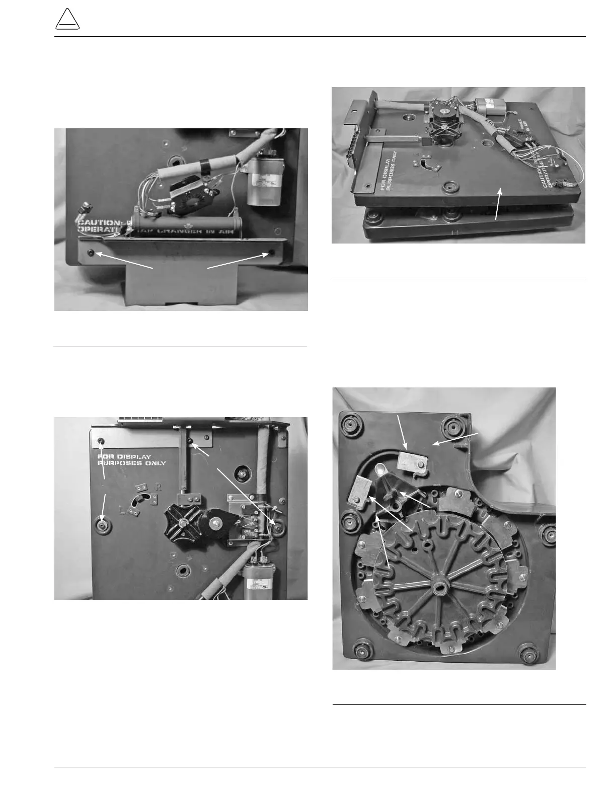
5. Lay the tapchanger assembly at on a work surface
with the tap contact studs down on the surface.
6. Using a 5/32 Allen wrench loosen and remove the two
pan head Allen screws from the tapchangermounting
bracket. (See Figure 158.)
Figure 158.
Tap-changer bracket mounting.
Bracket Fasten Screws
7. Use a 5/32 Allen wrench to loosen and remove the pan
head Allen screws fastening the front drive assembly
section and the contact panel assembly section togeth-
er. (See Figure 159.)
Figure 159.
Drive panel and contact panel fastening.
Screws
Screws
8. Lift the front drive assembly off of the contact assembly
and set aside. (See Figure 160.)
Figure 160.
Tap-changer sections.
Drive Assembly
Reversing Stationary Contact Removal
and Re-Assembly
1. The main moveable stationary contact must be locat-
ed on the neutral stationary contact located under the
reversing moveable contact arm. The reversing move-
able contact buttons must be located in the center
space between the VR and VL stationary contacts. (See
Figure 161.)
2. If not, by hand rotate the main moveable contact assem-
bly so that statement in step one is true.
3. The VR and VL stationary contact are reversible, or one
can be use for the other.
Figure 161.
Reversing stationary and reversing moveable.
Reversing Stationary
Contact VR
Reversing Stationary
Contact VL
Neutral Position
Reversing Moveable
Contact
Contact Panel