S225-12-1
65
!
SAFETY
FOR LIFE
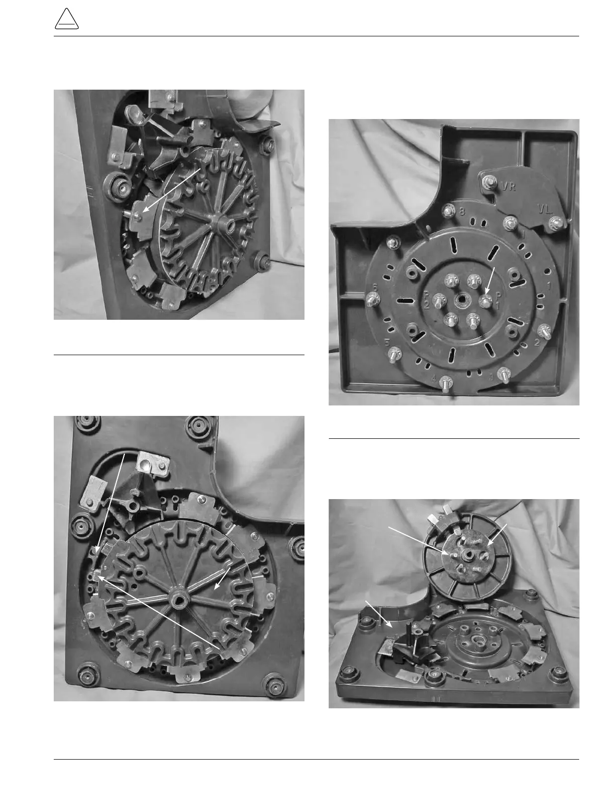
2. Push the contact stud through the mounting hole in the
contact panel. (See Figure 196.)
3. By hand, rotate the main moveable contact and Geneva
gear assembly so that the moveable contact is in the
stationary one contact position. (See Figure 197.)
Figure 196.
Stationary contact removal.
Figure 197.
Positioning of moveable contacts.
Stationary Contact
Contact One Position
Main Moveable
Contact Assembly
Moveable Contact
4. Use a 9/16 wrench or deep well 9/16 socket and ratchet
to remove the six nuts, lock washer, and flat washer
fastening the P1 and P2 slip ring studs to the contact
panel located in the center back of the stationary contact
panel. (See Figure 198.)
5. Facing the main moveable contacts and Geneva gear
assembly, pull forward removing the main contact
assembly and P1 and P2 slip ring assemblies from the
contact board assembly. (See Figure 199.)
Figure 198.
P1 and P2 stud hardware removal.
Figure 199.
Separating moveable contacts.
P1 & P2 Stud
Fastening Hardware
P1 & P2
Slip Rings
Contact Board
Assembly
Main Move-
able
and
Geneva Gear
Assembly