QD3 Quik-Drive Voltage Regulator Tap-Changer Manual
66
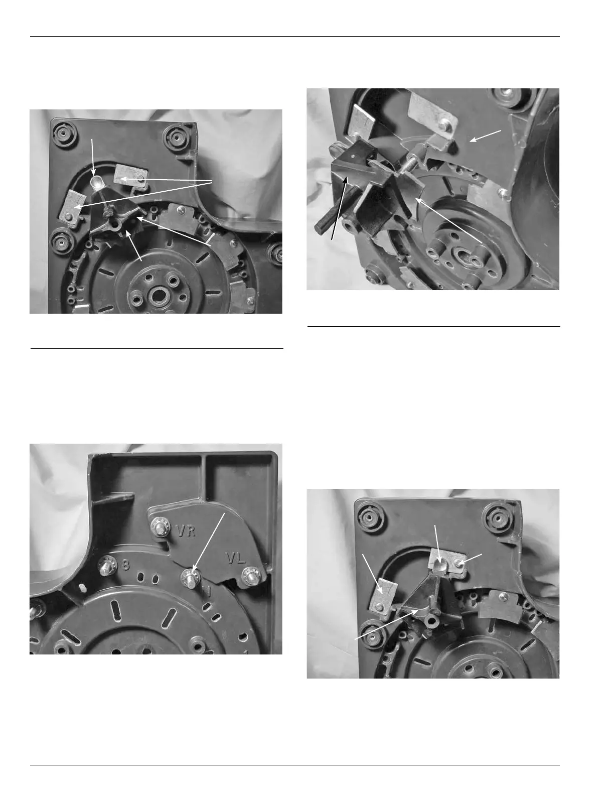
6. Rotate the reversing switch assembly, if not already
rotated, so that the contact buttons are in the center
space between the VR and VL stationary contacts as
though in the neutral position. (See Figure 200.)
7. Using a 9/16 wrench, or 9/16 socket and ratchet loosen
and remove the mounting nut on the stud of the reversing
switch assembly. The reversing switch assembly stud
is located between the reversing stationary contacts
VR and VL on the stationary contact assembly on the
contact panel. (See Figure 201.)
Figure 200.
Positioning of moveable reversing switch.
Figure 201.
Moveable reversing switch hardware.
Contact Button
Reversing
Stationary
Contacts
Neutral
Switch
Moveable
Reversing
Switch
Moveable
Reversing
Switch
Hardware
8. Pull out on the reversing moveable contact assembly
removing form the contact panel. (See Figure 202.)
9. Install the reversing switch assembly with the contact
buttons located between the VR and VL stationary
contacts. (See Figure 200.)
10. Place the brass flat washer, external tooth lock washer
and nut onto the reversing switch assembly stud.
Tighten and torque the hardware to 6070 poundinch
torque (6.7797.908 Nm).
11. Rotate the reversing switch assembly so that the button
contacts are on the VR reversing stationary contact.
(See Figure 203.) To identify the VR stationary contact
look for the ID marking on the contact panel.
Figure 202.
Removal of moveable reversing switch.
Moveable
Reversing
Switch
Figure 203.
Reversing moveable contact positioning.
Contact
Panel
Neutral
Stationary
Contact
Reversing
Moveable
Contact
Button
Reversing
Moveable
Contact
Assembly
VL Reversing
Stationary
Contact
VR Reversing
Stationary
Contact