S225-12-1
67
!
SAFETY
FOR LIFE
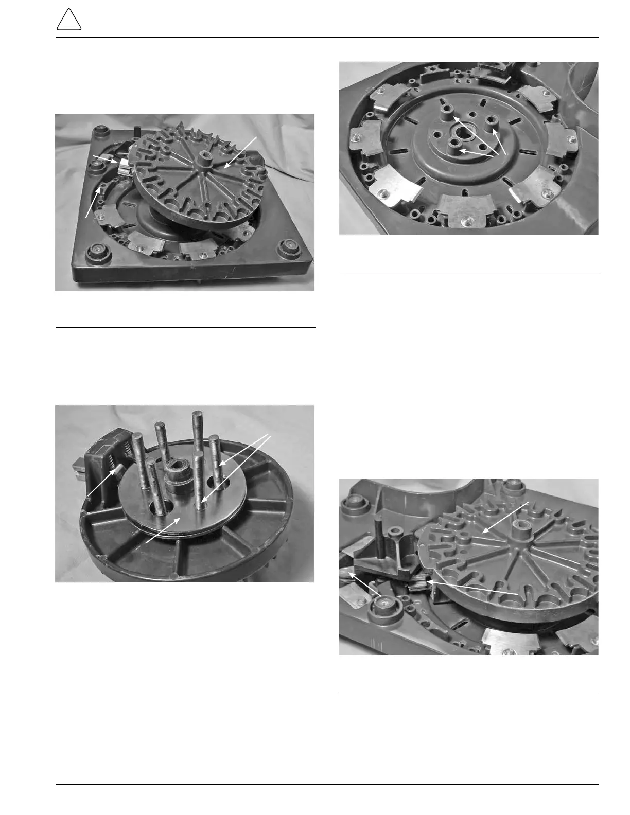
12. Align the Moveable Contact and Geneva Gear Assembly
so that the moveable contacts align to where the number
one stationary contact has been removed. (See Figure
204.)
13. Align the studs of the slip rings with the mounting holes
in the contact panel. The studs on the slip ring that is
between the left hand lower button contact will go into
the holes that have the high shoulder spacer as part of
the contact panel. (See Figures 205 and 206.)
Figure 204.
Moveable contact re-assembly.
Higher
Mounting
Shoulders
Stationary
Contact
Position
One
Moveable
Contact
Assembly
Figure 205.
Slip ring P1 and P2 studs.
Moveable
Contact
Button
Slip Ring
P1 and P2 Slip
Ring Studs
Figure 206.
P1 and P2 mounting holes.
Higher Mounting
Shoulders
14. You may need to rotate the slip ring assemblies in the
button contact to make the proper alignment.
15. Press on the moveable and Geneva contact assembly to
insert the studs.
16. You may find that after starting the studs, the moveable
and Geneva contact assembly will need to be rotated to
position the moveable contact so that the contacts are
not interfering with other stationary contacts during the
installation.
17. Rotate the main moveable contact Geneva gear assembly
onto the neutral stationary contact, located under
the reversing switch assembly, locating the reversing
moveable so that the button contact is between VR &VL
stationaries. (See Figure 207.)
Reversing
Moveable
Contact
Button
Moveable
Contact
Assembly
Neutral
Stationary
Contact
18. Place a flat brass flat washer, external tooth lock washer,
and 3/8 nut on each of the P1 and P2 slip ring studs and
tighten with a 9/16 wrench or socket and ratchet. Torque
the nut on the studs to 6070 poundsinch (6.7797.908
Nm).
Figure 207.
Positioning of reversing moveable contacts.