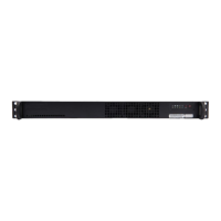
ONE SD-LAN Head
End Equipment
Quick Installation Guide
SD-LAN-000-HEEQUIP
| Page 13Qucik Installation I SD-LAN-000-HEEQUIP
Step 6
Step 7
Make sure outgoing cables are
routed and strain relieved properly to
housing
Connect jumpers from Head End
Active equipment to the appropriate
port on CCH panels
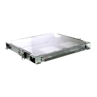
METHOD C. CCH Pigtailed Splice Cassettes
Step 1
Step 2
Step 3
Step 4
Step 5
Step 6
Use CCH Pigtailed Splice Cassettes
to interconnect Head Equipment and
outgoing ber cables
Terminate ber in CCH Splice
cassette using Corning standard
recommended procedure
(http://csmedia.corning.com/
opcomm/Resource_Documents/
SRPs_rl/003-895.pdf)
Insert CCH splice cassettes into
housing
Route ber in back of CCH housing
making sure the minimum bend
radius is not exceeded and
bers are not pinched or damaged
Make sure outgoing cables are
routed and strain relieved properly to
housing
Connect jumpers from Head End
Active equipment to the appropriate
port on CCH splice cassettes