20
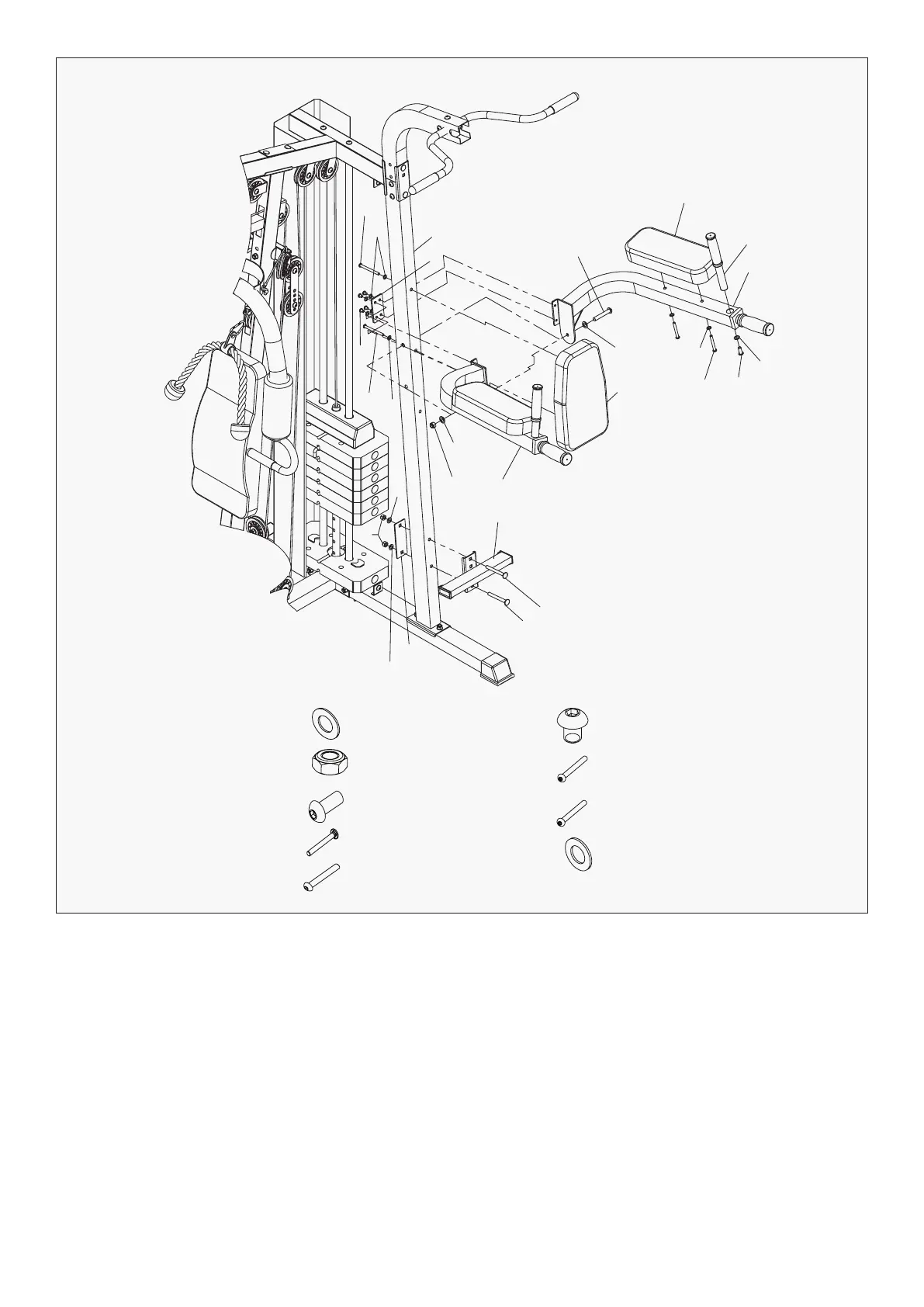
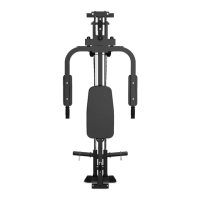
STEP 11
| ASSEMBLY INSTRUCTIONS
1. Attach the Left Dip Arm (#101) and the Right Dip Arm (#102) to the Vertical Frame (#91). Secure it
with 1x Carriage Bolt M10*70mm (#33), 2x Washer Φ10 (#14), 1x Aircraft Nuts M10mm (#20). Connect
the two arms (#101) and (#102) together by 4 Hex Bolts M8x10 (#72), 4 washers Ф8 (#39), 1 Plate
(4 holes) (#71).
2. Plug the Handle Bar (#103) into the hole of Right Dip Arm (#101) and (#102) with 2 Hex bolts M10x20 (#49).
3. Attach the Arm Pad (#106) to the Right and left Dip Arm. Secure it with 4 Allen Bolts M8*65mm (#110),
4x WasherФ8 (#39).
4. Attach the Padded Back Support (#108) to the Vertical Frame (#91). Secure it with 2x Allen Bolts
M8x85mm (#54), 2x Washer Ф8 (#39).
5. Attach the Foot Stand (#97) to the Vertical Frame (#91). Secure it with 2x Carriage Bolt M10 x 90mm
(#31), bracket (#22), 2x Washer Φ10 (#14), 2x Aircraft Nuts M10 (#20).
14
91
54
54
39
71
39
72
33
106
103
102
14
49
110
39
14
108
101
14
20
20
97
31
31
22
14
#14 Φ10 - 6pcs #72 M8x10 - 4pcs
#54 M8x85 - 2pcs
#110 M8x65 - 4pcs
#39 Φ8 - 8pcs
#20 M10 - 3pcs
#49 M10X20 - 2pcs
#31 M10x90 - 2pcs
#33 M10x70 - 1pc