9ASSEMBLY INSTRUCTIONS |
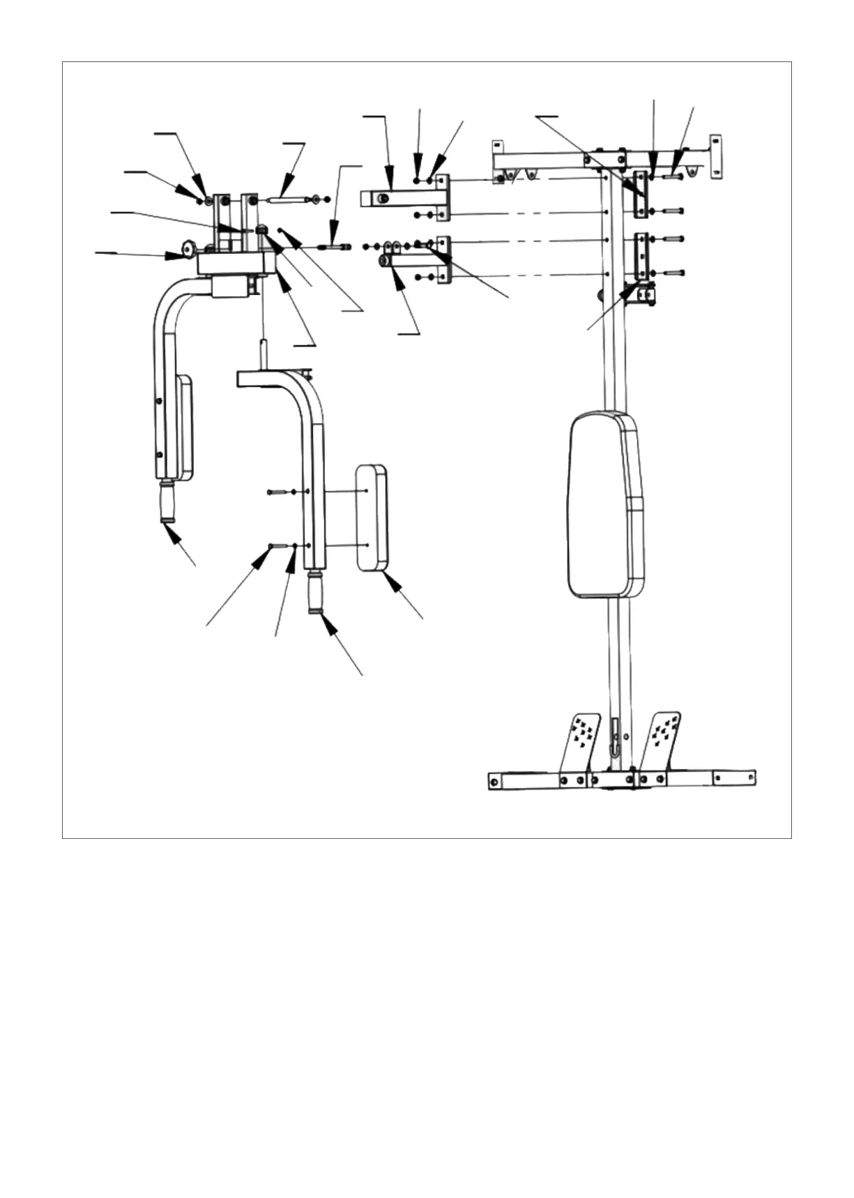
STEP 3
1. According to the diagram, place (#13) and (#14) to the front of (#3), and (#24) at the back, then tighten
with bolts (#31), flat spacer (#38) and nuts (#40).
2. According to the diagram, place (#12) on both sides of (#14) and pass through (#23) and tighten it
with the flat gasket (#37) and nut (#40).
3. Place (#28) inside (#13) as per the diagram, then insert in (#32) and tighten with flat gasket (#38)
and nut (#40). Screw on (#22).
4. Set (#2) onto (#12) according to the diagram, cover (#19) with bolts (#36) and nuts (#41). Attach (#9)
onto (#2) with flat pads (#39) and bolts (#35).
5. Repeat on the other side.
37
40
36
22
23
28
14
40
38
24
38
31
19
12
41
13
32
24
1
35
39
2
9