INSTALLATION
3
CL491 (11-04-19)
GENERAL INFORMATION
Tanks listed below are pre-charged, or filled with air at
the factory, to 40 pounds per square inch (PSI) (276kPa).
When installing tank, set tank pressure according to
Chart 1. To do this, bleed air from or add air to tank
through valve on top of tank.
NOTICE: Always set or check tank pre-charge with
NO WATER in tank or water pressure in system. If you
have already pumped water before setting or checking
pre-charge pressure, turn pump off. Open faucet until
there is no more water pressure. Set pre-charge in tank
according to Chart 1, then close faucet and turn pump
back on.
NOTICE: Replace and tighten air valve cap after
pressure is adjusted correctly. Failure to replace air
cap may allow loss of air pressure and lead to tank
waterlogging and bladder failure.
CHART 1- TANK PRECHARGE SETTINGS
When Pressure Switch
Setting Is:
Reduce Tank
Precharge (PSI) To:
20-40 PSI (138-276 kPa) 18 (124 kPa)
30-50 PSI (207-345 kPa) 28 (193 kPa)
40-60 PSI (276-414 kPa) 38 (262 kPa)
(The first number on the pressure switch is the pump
‘ON’ setting; the second number is the pump ‘OFF’
setting.)
Pre-charged storage tanks can be connected together
to increase the drawdown. Drawdown is the actual
amount of usable water available from when the tank
is full to when the pump turns on. Installing two tanks
of same size will double the drawdown supply, three
tanks will triple the drawdown supply, (Figure 1). Locate
pressure switch as shown. Tank and pressure switch
cannot be more than 10’ (3M) apart.
NOTICE: Tank capacity is different than drawdown.
Tank capacity is the actual physical volume of the sheet
metalthatmakesupthetank.
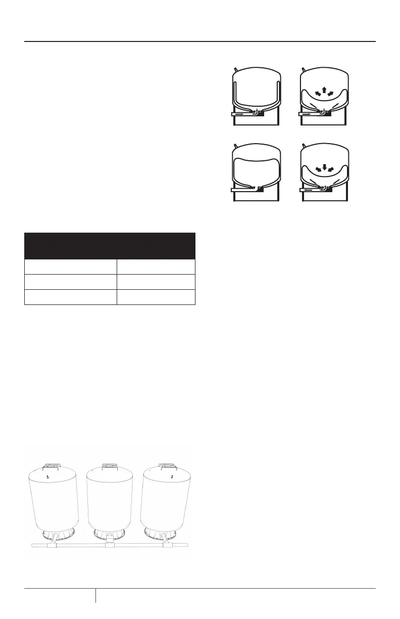
Operating Cycle
1. Tank nearly empty – air expands filling area above
bladder (Figure 2A).
2. Water enters tank – air is compressed above bladder as
it fills with water (Figure 2B).
3. Pump-up cycle completed – air compressed to OFF
setting of pressure switch (Figure 2C).
4. Water drawn from tank – compressed tank air forces
water out of bladder (Figure 2D).
5. Bladder empty – new cycle ready to begin (Figure 2A).
INSTALLATION
Connect discharge pipe from pump to a tee. Connect
one side of tee to tank flange and the other side of tee
to service. Use plastic or steel pipe as required. To
prevent leaks, use PTFE pipe thread sealant tape on
male threads of all threaded connections to tank.
NOTICE: To be sure pipe joints are not cross-threaded
and all threads are clean, make connections by hand
(without sealer) first. When threads are clean, remove
pipe, add PTFE tape, and remake connection. Tighten by
hand first; finish with pipe wrench.
When installing an elbow or nipple in the plastic tank
flange, tighten it hand tight plus 1-1/2 turns with a pipe
wrench. DO NOT OVERTIGHTEN!
Standard Tank Replacement
When replacing a standard tank in a water system with
a pre-charged tank, no bleeder orifices or Air Volume
Control (AVC) are required. When sizing a pre-charged
tank to replace a standard tank, the tanks should have
equivalent drawdowns. For example, model CLPT20
pre-charged tank has a drawdown of 5.8 gallons (22L)
and is equivalent to a 42 gallon standard tank that has a
drawdown of 4.3 gallons (16.3L).
Figure 2 - Tank Operating Cycle
WATER
WATER
WATER
Figure 1
Tanks
 Loading...