1
64.5
25
10
24.515
37
0.5
64.5
26
G1/4"-F
64.5
7.5 2235
65.5
DIN
71
clip
33.5
10
G1/4"-F
B
L
A
A
A
B
P 4.5/7 bar
Ø6
1.0 mm
1.2 mm
1.4 mm
2 3 4 5 6 7 8 9
Simultaneously active module number
Anzahl der gleichzeitig aktiven Module
nozzle ID
Düse ID
G1/8"-F
P = 4 bar
B
B
d
D
G1/4"-F
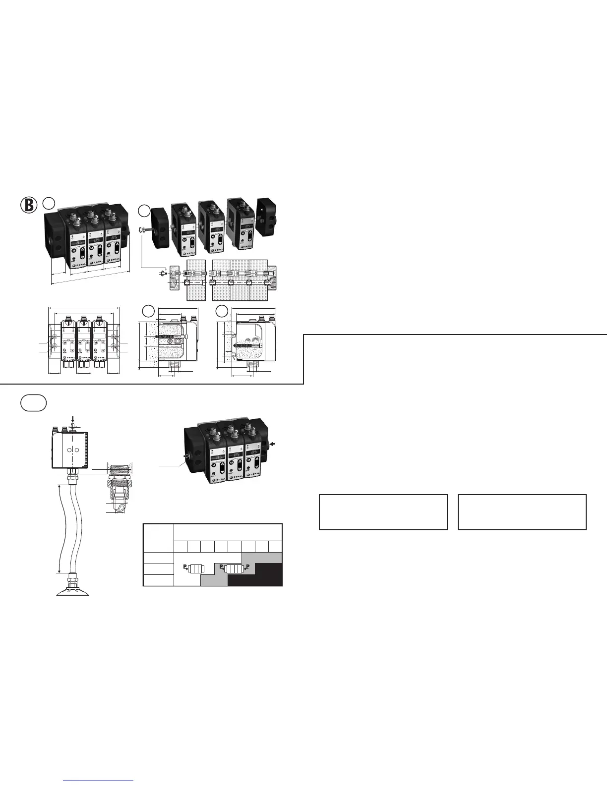
IV - TUBE CONNECTIONS
A- CONNECTION FOR PRESSURE SUPPLY
- 5µ filtered, non-lubricated air relevant to standard ISO 8573-1:2010
[4:5:4].
1- Stand-alone modules
- Push fitting for 6 mm OD tube (A).
- Network pressure P = 4.5 to 7 bar.
2- Islands
- Side connection on threaded port G1/8"-F (A), on one or both island
ends, depending upon simultaneously active number and size of
units: nozzle ID 1.0 mm, 1.2 mm or 1.4 mm.
Follow table recommendations.
- Pressure preferably regulated to 4 bar for energy savings and noise free
performance (island stacked modules have no integrated regulator).
B- VACUUM CIRCUIT CONNECTION
For an optimum performance with "Air saving control" it's a must to
maintain the airtightness of the vacuum network at all times. If there is
movement of the vacuum tube with respect to the module, a compresssion
fitting (illustration) is recommended to assure an air-tight connection.
see COVAL catalogue, fittings choice for tubes dxD= 4x6 mm, 6x8
mm, 8x10 mm.
Important: for short response times and minimum consumption it
is advised to reduce the volume to be evacuated.
While doing this, the module is installed closed to the suction pads
and the length L of the tube connecting the suction pads is as short
as possible.
Note : module's protection
- Vacuum entry sieve
A 200 µ sieve, integrated in port B, protects the module by stopping
any abrasive particle (sand…).
- Possible additional filter on vacuum circuit
In the rare cases of thin dust in wet environment, an adequate filter
will prevent any clogging:
see COVAL catalog, "vacuum circuit filters".
IV - ANSCHLÜSSE
A- ANSCHLUSS DER DRUCKVERSORGUNG
- Gefilterte, nicht geölte Luft, 5 µm gemäß Norm ISO 8573-1:2010
[4:5:4].
1- Autonome Module
- Schnellkupplung für Schlauch Ø 6 mm (A).
- Druck des Netzes: P = 4.5 bis 7 bar.
2- Inseln
- Anschluss an Gewindeöffnung G1/8"-F (A), auf einer oder auf beiden
Seiten der Insel, in Abhängigkeit von der Anzahl der gleichzeitig aktiven
Module und von ihrer Leistung : Düsen Ø 1 mm, 1,2 mm oder 1,4 mm.
Die Anweisungen der links stehenden Tabelle einhalten.
- Druck vorzugsweise zum Energiesparen und für ruhigen Betrieb auf
4 bar entspannt (die vereinten Module haben keinen integrierten
Druckminderer).
B- ANSCHLUSS AN VAKUUMKREISLAUF
Für einen zufriedenstellenden „Air Saving Control“, muss der Vakuumkreis-
lauf dauerhaft dicht sein. Wenn sich der Schlauch in Bezug zum Modul
bewegt, wird ein Anschluss mit geschraubter Kappe (Abbildung) empfohlen.
Siehe COVAL-Katalog, Auswahl der Schlauchanschlüsse dxD =
4x6 mm, 6x8 mm und 8x10 mm.
Wichtig: für kurze Reaktionszeiten und einen minimalen Verbrauch,
ordnet man das Modul möglichst nahe an den Saugnäpfen an. Dazu
und weil das Modul möglichst nahe an den Saugnäpfen angeordnet
wird, muss dafür gesorgt werden, dass die Länge L des Schlauches,
das sie mit dem Modul verbindet, möglichst kurz gehalten wird.
Hinweis: Schutz des Moduls
- Siebfilter am Eingang des Vakuums
In die Öffnung B ist ein Siebfilter zu 200 µ eingebaut, um das Modul
zu schützen und scheuernde Partikel aufzufangen (Sand usw.).
- Eventuell zusätzlicher Filter auf dem Vakuumkreislauf
In seltenen Fällen, wenn feiner Staub in feuchter Umgebung vorliegt,
vermeidet ein entsprechender Filter ein internes Verstopfen:
siehe Katalog COVAL „Filter für Vakuumkreisläufe“.
IV
- 3 -
B- INSELMODULE
1- Zusammengebaute Inseln
Wenn es sich um Module des gleichen Typs handelt, wird die
Insel zusammengebaut geliefert, zum Einbauen, Verbinden und
Anschließen bereit.
2- Zusammenbauen einer Insel
Die Module sind unterschiedlichen Typs und werden in Abhängigkeit
von den Erfordernissen der Anlage in Inseln angeordnet. Das
Zusammenbauen erfolgt durch einfaches Schrauben eines Moduls
auf das andere, mit einem Schraubendreher Torx T8 (Abbildung).
3- Befestigen einer Insel von vorn
mit 2 durchgehenden Schrauben Ø 4 mm.
4- Befestigung einer Insel auf DIN-Schiene
Der Befestigungsbausatz LEMFIXC besteht aus 2 Schrauben und 2
Clips, um jedes der Enden der Insel auszustatten. Die Insel wird auf
das DIN-Profil geclipst.
Anmerkung: Alle Maßangaben in mm.
B- ISLAND MODULES
1- Pre-assembled island
With all identical modules, the island is supplied all assembled,
ready for fixation and connections.
2- Island assembly
When different, the modules may be positionned into the island
according to the installation needs.
Assembly is easily made by screwing each module on the other,
using a T8 Torx screw driver (illustration).
3- Island mounting from front
2 protruding screws Ø 4mm.
4- Island mounting over a DIN rail
Fixing set LEMFIXC provides 2 screws and 2 clips to equip each
island end. The island may then be clipped over the DIN rail.
Note: All dimensions are in mm.
 Loading...