OUT
IN
(LEMAX90X
--
S / LEMAX90X
--
V / LEMAX90X
--
W)
B1 A1
2
1
4
3
2
1
4
3
OUT
24 V
5 V
0 V 0 V
IN
CDM8
OUT IN
CCM8
B2
B3
A2
(LEMAX90X
--
S)
2
1
4
3
2
1
4
3
24 V
1
➝
5 V
0 V
0 V
V
VI
PNP
NPN
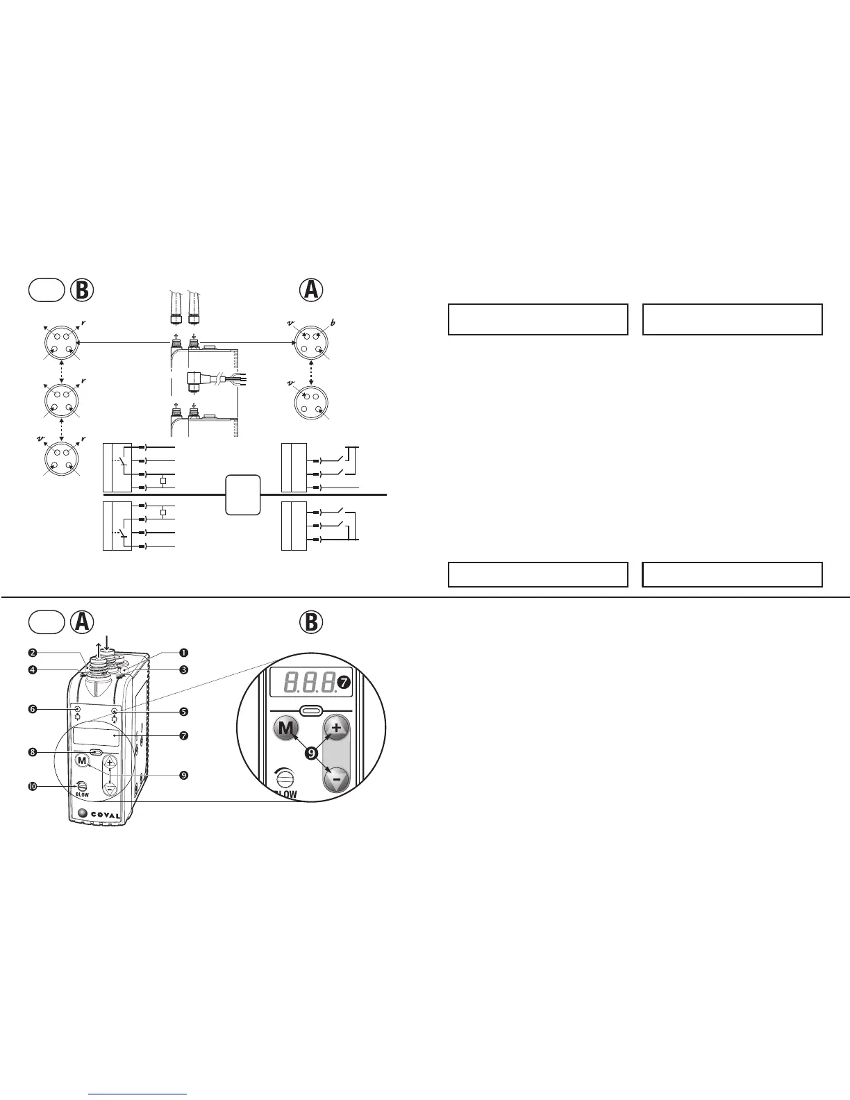
V - ELECTRICAL CONNECTIONS
The LEMAX vacuum pump must be used with power supply units
that provide a Protective Extra Low Voltage (PELV) and with an
isolation of the supply voltage according to EN60204.
The electrical connections to be made depend of the module use,
which will also correspond to a specific configuration illustrated in
chapter IX.
A- IN connections
PIN 3 (blue wire)
➞
0V permanent.
PIN 2 (white wire):
- LEMAX90X version
--
S / LEMAX90X version
--
V ➞ vacuum
command
v .
- Version LEMAX90X
--
W ➞ command
v = vacuum stop.
A1- Connection for blow-off controlled by specific signal
PIN 4 (black wire)
➞
blow-off command
b.
A2- Connection for automatic-timed blow-off (see VIII-3)
PIN 4 (black wire)
➞
no connection.
note : automatic-timed blow-off only on LEMAX90X
--
S.
B- OUT connections
Permanent supplies:
PIN 3 (blue wire)
➞
0V PIN 1 (brown wire)
➞
24V
PIN 4 (black wire)
➞
switching output
r
B1- Connection for "ASC missing" signal (see VIII-2)
PIN 2 (white wire)
➞
output “ASC missing” signal + 5V DC output NO.
B2- Connection for "vacuum level" signal (see VIII-2)
PIN 2 (white wire)
➞
output analogic signal 1 to 5V DC.
B3-Connection version LEMAX90X
--
SC14
PIN 2 (white wire)
➞
vacuum control
v
VI - DIALOGUE PANEL
A- Dialogue
Visual indicator v signal vacuum command (green).
Visual indicator
b signal blow-off command (orange).
Vacuum manual override.
Blow-off manual override.
Operation indicator "vacuum" (green).
Operation indicator "blow-off"(orange).
3 digit digital display.
Visual indicator "gripped product" (green).
Keyboard: configurations and settings.
Blow-off flow regulator.
B- Configuration
3 digit digital display
:
- configuration and diagnostics interface
- production follow-up.
Keyboard
:
- M: mode selection.a
- + & −: value selection.
V - ELEKTROANSCHLÜSSE
Die LEMAX-Vakuumpumpe erfordert die Verwendung von
Schutzkleinspannung (= PELV - Protective Extra Low Voltage)
und eine sichere Trennung von der Versorgungsspannung nach
EN60204.
Die herzustellenden elektrischen Anschlüsse hängen vom
Gebrauch des Moduls ab, von dem auch ein Parametrieren, in
Kapitel IX angegeben, abhängt.
A- Anschlüsse IN
PIN 3 (blauer Leiter)
➞
0V permanent.
PIN 2 (weißer Leiter):
- Version LEMAX90X
--
S / LEMAX90X
--
V ➞ Vakuumsteuerung
v .
- Version LEMAX90X
--
W ➞ command
v = Vakuumstopp.
A1- Anschluss für durch spezifisches Signal gesteuertes Abblasen
PIN 4 (schwarzer Leiter)
➞
Abblassteuerung b .
A2-Anschluss für Self-Timed Abblasen (siehe VIII-3)
PIN 4 (schwarzer Leiter)
➞
kein Anschluss.
Hinweis: Das Self-Timed Abblasen ist nur auf LEMAX90X
--
S
verfügbar.
B- Anschlüsse OUT
Ständige Versorgungen:
PIN 3 (blauer Leiter)
➞
0V PIN 1 (brauner Leiter)
➞
24V
PIN 4 (schwarzer Leiter)
➞
Signalausgang
r
B1- Anschluss für das Signal „ohne ASC“ (siehe VIII-2)
PIN 2 (weißer Leiter)
➞
Signalausgang „ohne ASC“ + 5 V DC NO.
B2- Anschluss für das Signal „Vakuumlevel“ (siehe VIII-2)
PIN 2 (weißer Leiter)
➞
Ausgang für Analogsignal 1 bis 5 V DC.
B3- Anschlussversion LEMAX90X
--
SC14
PIN 2 (weißer Draht)
➞
Vakuumkontrolle
v
VI - ANZEIGE UND BEDIENFELD
A- Zustand und Bedienfeld
Anzeigelampe Steuersignal des Vakuums v (grün).
Anzeigelampe Steuersignal des Abblasens
b (orange).
Manuelles Steuern des Vakuums.
Manuelles Steuern des Abblasens.
Statusanzeige „Vakuums“ (grün).
Statusanzeige „Abblasen“ (orange).
Anzeige 3-Stellig 7 Ziffern.
Anzeige „Objekt angesaugt“ (grün).
Tastatur: Parametrierung und Einstellung.
Einstellung des Abblas-Volumenstroms.
B- Konfiguration
Anzeige 3-Stellig 7 Ziffern
:
- Bedienfeld für Parametrierung und Einstellung.
- Betriebsüberwachung.
Bedientastatur
:
- M: Auswahl der Betriebsart.
- + & −: Auswahl des Werts.
BN: brown
BK: black
BU: blue
WH: white
The switching type of the inputs / outputs can be set to PNP ( by
default) or NPN (see IX-4).
Der Schaltmodus der Ein- / Ausgänge ist in PNP (Standard) oder
NPN (siehe IX-4) konfigurierbar.
+ 24V DC
v
b
0V DC
LEMAX PNP IN
2 WH
4 BK
3 BU
LEMAX NPN IN
v
b
0V DC
2 WH
4 BK
3 BU
R
L
1 BN
+ 24V DC
5 V DC / 1➞5V
r
0V DC
LEMAX PNP OUT
2 WH
4 BK
3 BU
R
L
1 BN
+ 24V DC
r
5 V DC / 1➞5V
0V DC
LEMAX NPN OUT
4 BR
2 WH
3 BU
2
1
4
3
24 V
0 V
- 4 -
 Loading...