4
GENERAL INSTALLATION INSTRUCTIONS
Ensure gas supply and gas type, as shown on unit nameplate, agree.
Unit installaon must conform with the Naonal Fuel Gas Code, ANSI Z223.1/NFPA 54, the
Naonal Gas Installaon Code, CSA-B149.1, or the Propane Installaon Code, CSA-B149.2 as
applicable and in accordance with local codes.
Screw legs into the permanently fastened nuts on the four corners of the unit and ghten by hand.
Level the unit by turning the adjustment screw at the boom of each leg. Do not slide unit with
legs mounted, li if necessary to move unit.
Pipe threading compound must be resistant to the acon of liquefied petroleum gases.
Cauon: DO NOT use an open flame to check for leaks. Check all gas piping for leaks with a soap
and water soluon before operang unit.
THESE UNITS ARE SUITABLE FOR INSTALLATION ON NON-COMBUSTIBLE SURFACES ONLY.
Combusble clearances:
6" sides (152 mm) 6" rear (152 mm) 4" floor (102 mm)
Noncombusble clearances:
0" sides ( 0 mm) 0" rear ( 0 mm) 4" floor (102 mm)
Do not obstruct the flow of combuson and venlaon air under the unit by the legs or behind
the unit by the flue.
Adequate clearance for air openings into the combuson chamber is required. Do not place
objects between the boom of the unit and the counter top.
There must be adequate clearance for removal of the front panel. All major parts except the
burners are removable thru the front if the gas line is disconnected.
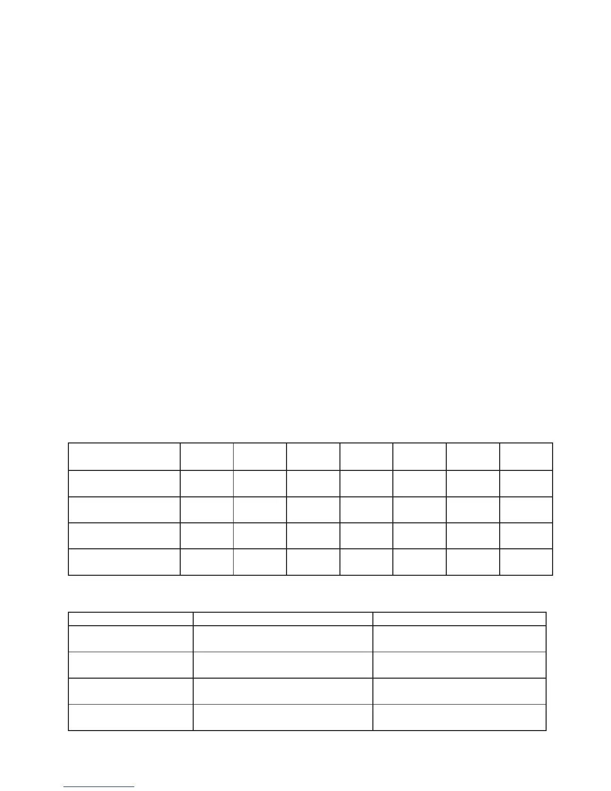
SPECIFICATIONS AND DIMENSIONS
MODEL WIDTH
IN. (MM)
DEPTH
IN. (MM)
HEIGHT
IN. (MM)
# OF
BURNERS
BTU/PER
NAT/LP
TOTAL
BTU/Hr
Pressure
In.w.c
G15
G15T
15(381) 26.8(680) 16.3(415) 1 30,000 30,000 6/10
G24T
24(610) 26.8(680) 16.3(415) 2 30,000
60,000 6/10
G36
G36T
36(915) 26.8(680) 16.3(415) 3 30,000
90,000 6/10
G48
G48T
48(1220) 26.8(680) 16.3(415) 4 30,000
12,0000 6/10
Note: regulator – 75mm/3.25 inch depth. Dimensions above do not include regulator.
Griddle Surface Dimensions