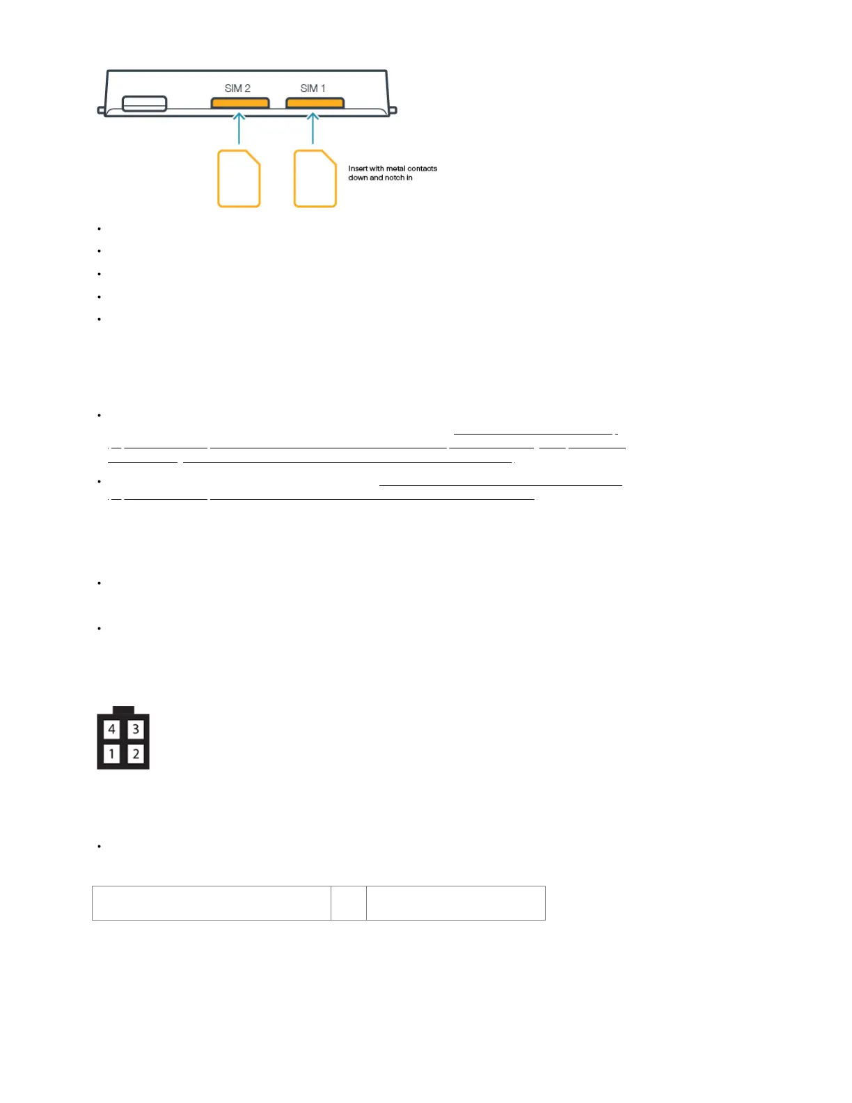
STEP 2: If using a MC400 modular modem, insert activated 2FF-sized SIM card(s) into the modem.
Insert the card into the SIM1 slot, metal contacts down and notch in.
Insert the secondary SIM into the SIM2 slot, if desired.
Slide the MC400 modular modem into the IBR1700, Cradlepoint logo side up, USB plug first.
Replace the modem door and secure with the screws.
Remove the plastic port covers from the modem door before returning the cover to the router.
Note: The MODEM COVER must be replaced, or the modem will not power on.
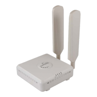
STEP 3: Set up the Antenna and WiFi Configuration.
The IBR1700 includes three (3) independent WiFi radios, allowing for a much more customizable and robust experience when using WiFi. For more
information on configuring and using the IBR1700's WiFi, please view this article: NCOS: 6.5 IBR1700 WiFi Radio Setup
(https://customer.cradlepoint.com/s/article/NCOS-6-5-IBR1700-WiFi-Radio-Setup?r=110&ui-knowledge-components-aura-
actions.KnowledgeArticleVersionCreateDraftFromOnlineAction.createDraftFromOnlineArticle=1).
There are many antennas options for the IBR1700. Refer to the Vehicle Installation Guide for COR Series Mobile Routers
(https://customer.cradlepoint.com/s/article/Vehicle-Installation-Guide-for-COR-Series-Mobile-Routers)for information about selecting an antenna option
that works best for you.
STEP 4: Connect the power source.
The 4-pin power/GPIO cable connects directly to the router and is intended for connecting to a DC power source.
Note: If installation requires building your own cable, you must use a Molex Micro-fit 3.0 Dual Row, 4-circuit connector.
Refer to the following for pin configuration to ensure the cables are connected appropriately:
PIN Wire Color Definition Details
1 Black Ground Ground to the vehicle chassis
2 Red Power VDC battery constant
3 Orange Input VOC ignition sensing accessory input
4 Blue Output General purpose I/O (GPIO)
(Optional) Connect to the 2x10 GPIO Port
Note: If installation requires building your own cable, you must use a Molex Micro-fit 3.0 Dual Row, 20- circuit connector.
Diagram Pin Details