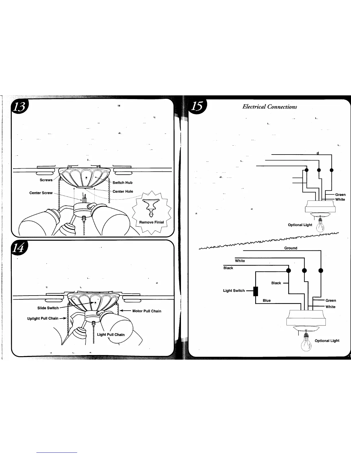
Optional Light Kit Installation
Remove three screws from side of switch hub (as shown in figure below).
Remove hub cover from hub and pop out center plug. Carefully thread
wires from light kit through the center hole in hub cover. At this point
attach light kit into hub cover by screwing ce~ter all-thread fr~m~light kit
into the center hub cover. Lock the all-thread m place on the mSlde of the
hub using the 3/8" nut provided. Attach white wire from light kit to
white wire in hub, using wire nuts. Next, attach black wire from light kit
to blue wire in switch hub. Carefully push wires up into hub and replace
hub cover using screws removed earlier.
Operation Instructions
1. The sequence of operation for the motor pull/chain switch is OFF-HI-
MED-LOW.
2. Push the slide switch RIGHT for FORWARD, and LEFT for REVERSE
action of the blades.
3. The pull chain switch for the lighting is two positions - ON/OFF.
4. The pull chain switch for the uplighting is on/off. NOTE: Uplighting takes
3-60W Candelabra bulbs (not incfuded).
A
-12-
~
CAUTION: Evenifyour fan is mounted with the bladesmore than 7 feetfrom the
floor,be carefulto avoidplacingyour raisedarmsor any object in the path of the blades.
Connect black and blue (if provided) fan wires to black outlet wire.
Connect white fan wire to white outlet wire and green grounding lead
wire from the grounding conductor to the supply circuit (see figure A).
Use wire connectors provided with your fan. No loose strands or loose
connections should be present. Mter wires have been connected, they
must be spread apart so the green and white are on one side of the outlet
box and the black and blue are on the other side. Turn •
splices upward and carefully
Groun
push all wiring into outlet
White
box. For optional wall
Black
control see figure B or .
Figure C for alternate wiring.
Blue
When wall switches are employed,
Black
switches should be UL listed
for use with ceiling fan.
NOTE: Make sure fan on/off switch
is always at "high speed" location if
your fan is controlled by additional Figure A
wall switch.
Figure B