EasyManua.ls Logo

Craftsman 161.210400 User Manual

Craftsman 161.210400
64 pages
To Next Page IconTo Next Page
Page #1 background imageLoading...
Page #1 background image
IIIIIIIII I
2-170701
I [11 II ........
I II II - --_
l
Sears
k ............. . ......
owners
manual
MODEL NO.
161.210400
Caution:
Read Rules For
Safe Operation
and Complete
Operating Test
Procedures
Carefully
............ ........ . .....
PRINTED iN U.S.A.
.;_(/ )-
CRRFTSHRN
ENGINE ANALYZER
FOR 12& 24 VOLT SYSTEMS
. OPERATING INSTRUCTIONS
SAFETY RULES
TUNE- UP PROCEDURES
REPAIR PARTS
,, ,,,, , ,, ,,,,,, , ,I .......... ' I I II Illl 11 IIIIIII IIII 11
SEARS, ROEBUCK AND CO. U.S.A.
CHICAGO, ILLINOIS 6068.4 ......
2-17070_

Table of Contents

Question and Answer IconNeed help?

Do you have a question about the Craftsman 161.210400 and is the answer not in the manual?

Craftsman 161.210400 Specifications

General IconGeneral
Model161.210400
CategoryMeasuring Instruments
TypeDigital Caliper
DisplayLCD
Units of MeasureInches/Millimeters
Power SourceSR44 Battery

Summary

Sears Owners Manual

Craftsman Engine Analyzer Overview

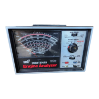
General introduction to the engine analyzer for specific voltage systems.

Safety Rules

Essential safety precautions for using the engine analyzer.

Safe Automotive Testing Rules

Breaker Point Ignition System Connections

Electronic Ignition System Connections

Starting and Charging System Tests

Test 1: Starting and Cranking Voltage

Procedure for testing starting and cranking battery voltage.

Test 2: Starter Current Draw

Procedure for measuring starter current draw.

Starter Circuit Voltage Loss Test

Test 3: Starter Circuit Voltage Loss

Procedure for testing voltage drop in the starter circuit.

Charging System Voltage and Current Tests

Test 4: Charging System Voltage and Current

Procedure for testing charging system voltage and current.

Alternator and Battery System Tests

Test 5: Alternator Condition

Procedure for assessing the alternator's overall condition.

Test 6: Alternator Full Field

Procedure for testing the alternator at full field output.

Voltage Regulator and Battery Tests

Test 7: Voltage Regulator

Procedure for testing and adjusting the voltage regulator.

Test 8: Battery

Procedure for testing the vehicle battery condition.

Ohmmeter and Diode Tests

Test 9: Ohms Test Procedure

Procedure for using the ohmmeter function.

Alternator Rotor/Stator and Primary Coil Voltage

Test 11: Primary Coil Voltage

Procedure for checking primary coil voltage.

Breaker Point Resistance Test

Test 12: Breaker Point Resistance

Procedure for testing breaker point resistance.

Dwell Adjustment for Breaker Point Systems

Test 13: Dwell Adjustment Procedure

Procedure for adjusting dwell angle on breaker point systems.

Electronic Ignition Dwell Angle Tests

Test 15: Dwell Angle (Electronic Ignition)

Procedure for checking dwell angle on electronic ignition systems.

Ignition Timing and Advance Systems

Test 16: Initial Ignition Timing

Procedure for setting and checking initial ignition timing.

Test 17: Timing Advance Systems

Testing mechanical and vacuum advance systems.

Carburetor Mixture Adjustment

Test 18: Carburetor Mixture Adjustment

Procedure for adjusting carburetor air/fuel mixture.

Carburetor Adjustments and Solenoids

Test 19: Carburetor Curb Idle Speed

Procedure for adjusting the carburetor's curb idle speed.

Ignition Coil Primary Resistance Test

Test 23: Ignition Coil Primary Resistance

Procedure for testing ignition coil primary resistance.

Ignition Coil Secondary Resistance

Secondary Resistance Measurement

Procedure for testing ignition coil secondary resistance.

Ignition Cable Resistance Test

Test 24: Ignition Cable Resistance

Procedure for testing ignition cable resistance.

Ballast Resistor Test

American Motors Electronic Ignition System

Chrysler Electronic Ignition System

Ford Electronic Ignition System

Delco HEI Ignition System (In-Cap Coil)

Delco HEI Ignition System (Separate Coil)

GM C-3/C-4 System (Computer Command Control)

Related product manuals