4 Afterthetemplatebracketshavebeencorrectlyposi-
tionedonthetemplatesecurelytightenthefourscrews
holdingthe template brackets to the template
5 Remove the template assembly from the base and set it
aside for now
6 Align the other template assembly in the same manner
IT SHOULD BE NOTED THAT YOU MAY FIND, THAT
AFTER MAKING SOME SAMPLE CUTS, SLIGHT
FIGURE 25
TEMPLATE BRACKET ,\
THE TEMPLATE EXTENDS
BEYOND THE TEMPLATE
BRACKET
ADJUSTMENTS MAY BE REQUIRED HOW TO MAKE
THESE ADJUSTMENTS IS EXPLAINED IN TWO OF THE
FOLLOWING SECTIONS: "TROUBLESHOOTING FOR
HALF BLIND JOINTS" or "TROUBLESHOOTING FOR
OPEN (THROUGH) JOINTS"
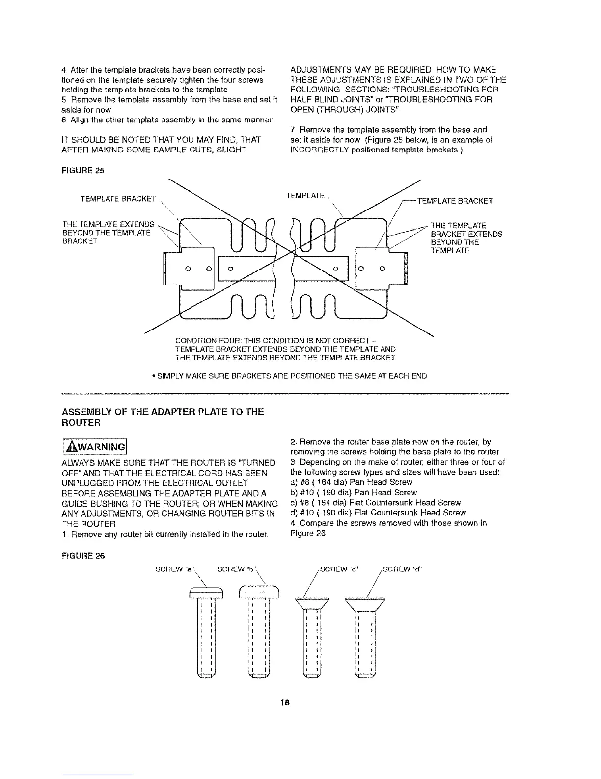
7 Remove the template assembly from the base and
set it aside for now (Figure 25 below, is an example of
INCORRECTLY positioned template brackets )
TEMPLATE ,
\,,\
o o
BRACKET EXTENDS
BEYOND THE
TEMPLATE
CONDITION FOUR: THIS CONDITION IS NOT CORRECT -
TEMPLATE BRACKET EXTENDS BEYOND THE TEMPLATE AND
THE TEMPLATE EXTENDS BEYOND THE TEMPLATE BRACKET
• SIMPLY MAKE SURE BRACKETS ABE POSmONED THE SAME AT EACH END
ASSEMBLY OF THE ADAPTER PLATE TO THE
ROUTER
[A¢kWARNING]
ALWAYS MAKE SURE THATTHE ROUTER IS q*URNED
OFF" AND THATTHE ELECTRICAL CORD HAS BEEN
UNPLUGGED FROM THE ELECTRICAL OUTLET
BEFORE ASSEMBLING THE ADAPTER PLATE AND A
GUIDE BUSHING TO THE ROUTER; OR WHEN MAKING
ANY ADJUSTMENTS, OR CHANGING ROUTER BITS IN
THE ROUTER
1 Remove any router bit currently installed in the router
FIGURE 26
SCREW ':a_'_,
i i
J I
t I
I I
1 I
t I
SCREW "b"_\
I I
I I
I I
t I
I I
I I
I I
I I
I I
I I
i i
2 Remove the router base plate now on the router, by
removing the screws holding the base plate to time router
3 Depending on the make of router, either three or four of
the loIIowing screw types and sizes will have been used:
a) #8 ( 164 dia) Pan Head Screw
b) #t0 (I90 din) Pan Head Screw
c) #8 ( 164 din) Flat Countersunk Head Screw
d) #10 ( t90 dia) Flat Countersunk Head Screw
4 Compare the screws removed with those shown in
Figure 26
SCREW 'c"
I 1
I 1
I 1
i 1
i t
SCREW "d"
I t
i *
18
 Loading...