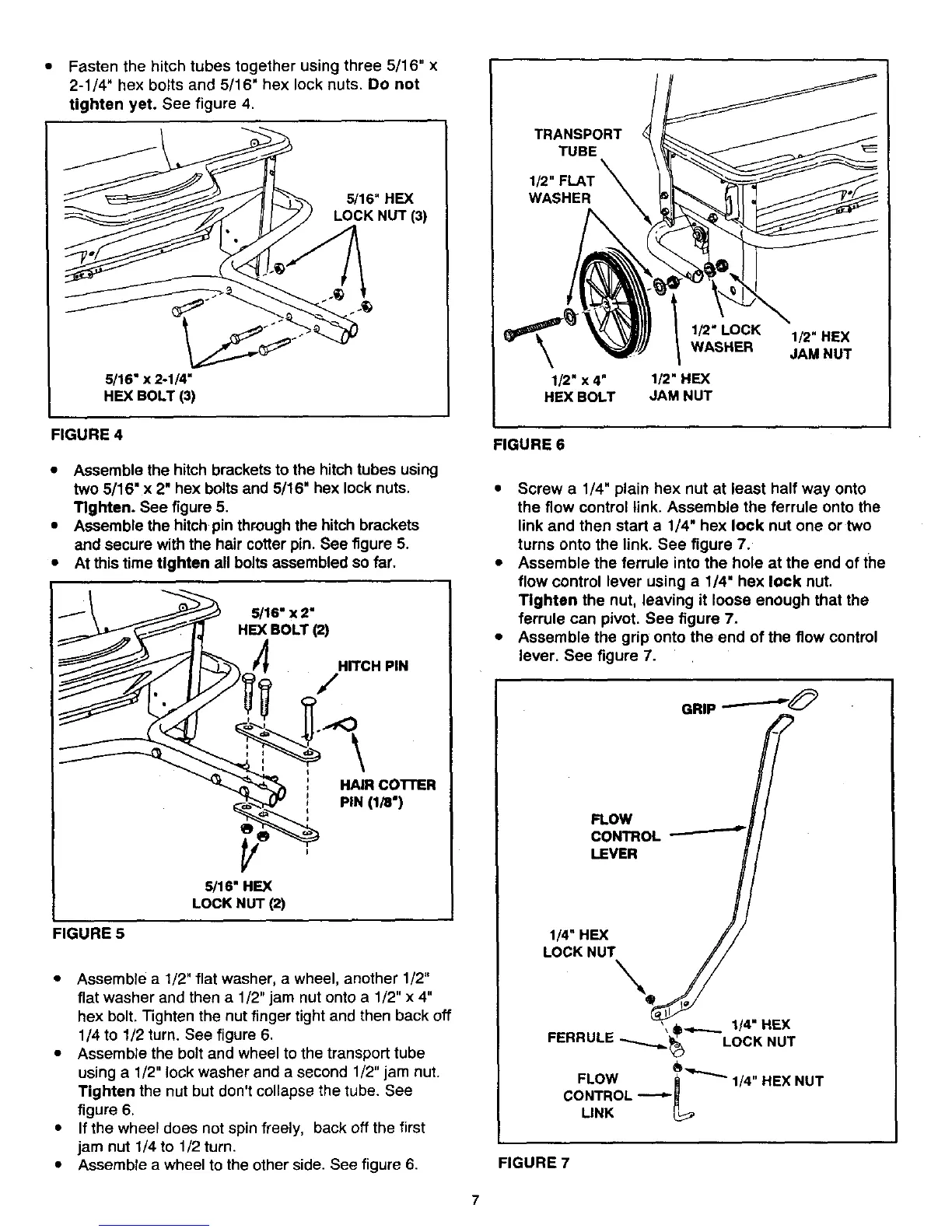
• Fasten the hitch tubes together using three 5/16" x
2-1/4" hex bolts and 5/16" hex lock nuts. DO not
tighten yet. See figure 4.
5/16" HEX
LOCK NUT (3)
5116"x 2-114"
HEX BOLT (3)
FIGURE 4
• Assemble the hitch brackets to the hitch tubes using
two 5/16" x 2" hex bolts and 5/16" hex lock nuts,
Tighten. See figure 5.
• Assemble the hitch pin through the hitch brackets
and secure with the heir cotter pin. See figure 5.
• At this time Ughten all bolts assembled so far.
/16 HEX
L LOCK NUT 12)
HITCH PIN
HAIR CO'I'rER
PiN (1/8")
FIGURE 5
• Assemble a 1/2" flat washer, a wheel, another 1/2"
flat washer and then a 1/2" jam nut onto a 1/2" x 4"
hex bolt. Tighten the nut finger tight and then back off
1/4 to 1/2 turn. See figure 6.
• Assemble the bolt and wheel to the transport tube
using a 1/2" lock washer and a second 1/2" jam nut.
Tighten the nut but don't collapse the tube. See
figure 6.
• If the wheel does not spin freely, back off the first
jam nut 1/4 to 1/2 turn.
• Assemble a wheel to the other side. See figure 6.
TRANSPORT
TUBE
WASHER
\
1/2" x 4"
HEX BOLT
I_"LOCK
WASHER
1/2" HEX
JAM NUT
I_"HEX
JAM NUT
FIGURE 6
• Screw a 1/4" plain hex nut at least half way onto
the flow control link. Assemble the ferrule onto the
link and then start a 1/4" hex lock nut one or two
turns onto the link. See figure 7.
• Assemble the ferrule into the hole at the end of the
flow control lever using a 1/4" hex lock nut.
Tighten the nut, leaving it loose enough that the
ferrule can pivot. See figure 7.
• Assemble the grip onto the end of the flow control
lever. See figure 7.
GRIP --,-'--"_0
FLOW
CONTROL _
LEVER
114"HEX
//
,, _.,,_.._.. 114"HEX
FERRULE ..,.,...,..__ LOCK NUT
_"-"'_'_ 1/4" HEX NUT
FLOW
CONTROL J_
LINK L_
FIGURE 7
7