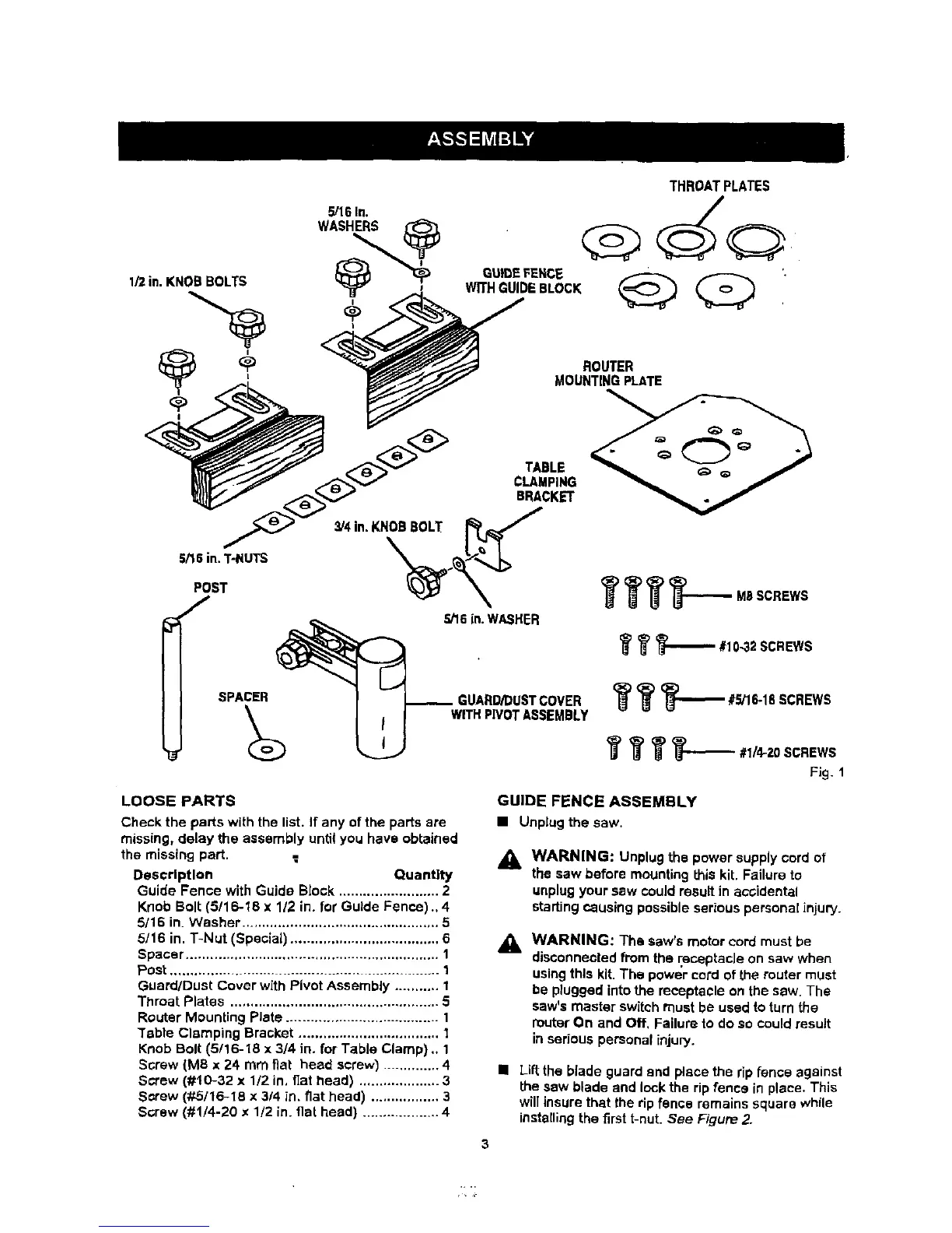
THROAT PLATES
5/16 In.
ROUTER
MOUNTING PLATE
Fig. 1
LOOSE PARTS
Check the parts with the list. If any of the parts are
missing, delay the assembly until you have obtained
the missing part.
Description Quantity
Guide Fence with Guide Block ......................... 2
Knob Bolt (5/16-18 x 1/2 in. for Guide Fence)., 4
5/16 in. Washer ................................................. 5
5/16 in. T-Nut (Special) ..................................... 6
Spacer ............................................................... 1
Post ................................................................ 1
Guard/Dust Cover with Pivot Assembly ........... I
Throat Plates .................................................... 5
Router Mounting Plate ...................................... 1
Table Clamping Bracket ................................... 1
Knob Bolt (5/16-18 x 3/4 in. for Table Clamp) .. 1
Screw (MS x 24 mm fiat head screw) .............. 4
Screw (#10-32 x 1/2 in, flat head) .................... 3
Screw (#5/16-18 x 3/4 in. fiat head) ................. 3
Screw (#1/4-20 x 1/2 in. flat head) .................. 4
GUIDE FENCE ASSEMBLY
• Unplugthe saw,
A
WARNING: Unplugthe power supplycord of
the saw beforemountingthis kit. Failure to
unplugyoursew couldresult in aooiclental
startingcausing possibleseriouspersonalinjuw.
WARNING: The saw's motor cord must be
disconnected from the receptacJe on saw when
using this kit. The power cord of the muter must
be plugged into the receptacle on the saw. The
saw's master switch must be used to turn the
router On and Off, Failure to do so could result
in serious personal injury.
• Lift the blade guard end place the rip fence against
the sew blade and lock the rip fence in place. This
will insure that the rip fence remains square while
instetling the first t-nut. See Figure 2.
3