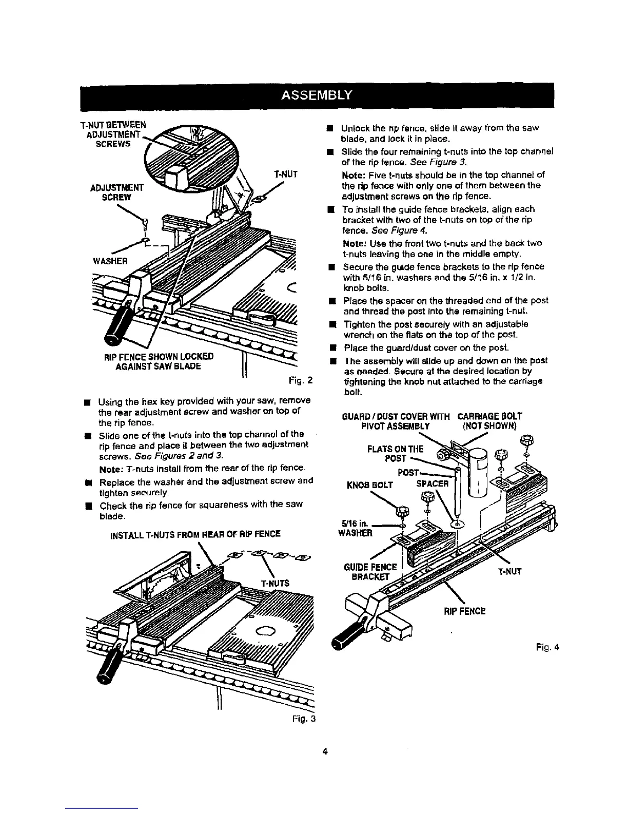
T-NUTBETWEEN
ADJUSTMENT
SCREWS
ADJUSTMENT
SCREW
L
T-NUT
WASHER
RIPFENCE SHOWN LOCKED
AGAINST SAWBLADE
Fig. 2
• Using the hex key provided with your saw, remove
the rear adjustment screw and washer on top of
the rip fence.
• Slide one of the t-nuts into the top channel of the
rip fence and place it between the two adjustment
screws. See Figures 2 and 3.
Note: T-nuts install from the rear of the rip fence.
• Replace the washer and the adjustment screw and
tighten securely.
[] Check the rip fence for squareness with the saw
blade.
INSTALLT-NUTS FROM REAR OF RIP FENCE
• Unlock the rip fence, slide it away from the saw
blade, and lock it in place.
• Slide the four remaining t-nuts into the top channel
of the rip fence. See Figure 3,
Note: Five t-nuts should be in the top channel of
the rip fence with only one of them between the
adjustment screws on the rip fence.
[] To install the guide fence brackets, align each
bracket with two of the t-nuts on top of the rip
fence. See Figure 4.
Mote: Use the front two t-nuts and the back two
t-nuts leaving the one in the middle empty.
• Secure the guide fence brackets to the rip fence
with 5116 in. washers and the 5/16 in, x 1/2 in.
knob bolts.
• Place the spacer on the threaded end of the post
and thread the post into the remaining t-nut,
[] Tighten the post securely with an adjustable
wrench on the flats on the top of the pest.
• Place the guard/dust cover on the post.
• The assembly will slide up and down on the post
as needed. Secure at the desired location by
tightening the knob nut attached to the carriage
bolt.
GUARD/ DUSTCOVERWITH CARRIAGE [3OLT
PIVOTASSEMBLY (NOT SHOWN)
FLATSONTHE Y
POST
KNOB BOLT SPACER
,_16in.,
WASHER
T-HUTS
GUIDE FENCE T-NUT
BRACKET
RIPFENCE
Fig. 4
Fig. 3
4