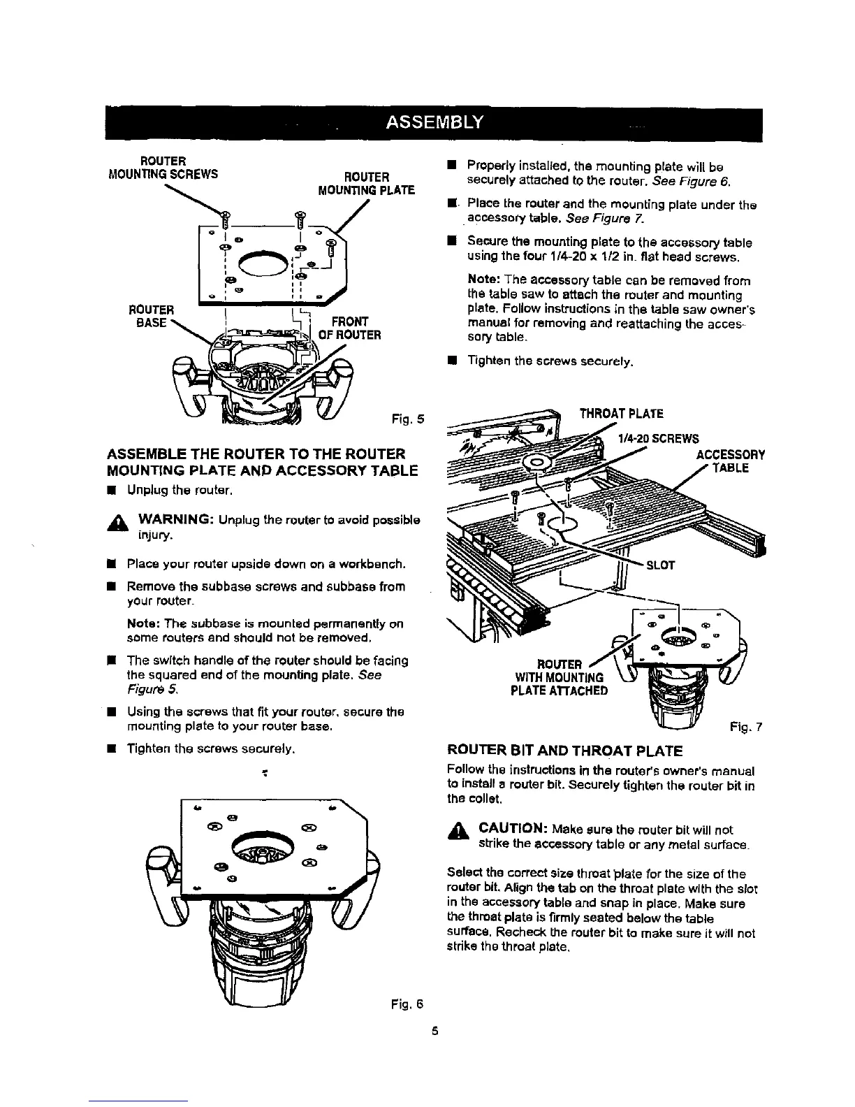
ROUTER
MOUN_NG SCREWS ROUTER
MOUN_NG PLATE
BOUTER _
BASE_ ! FRONT
=ROUTER
• Properly installed, the mounting plate will be
secvrely attached to the router. See Figure 6.
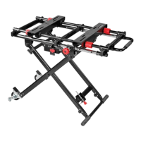
J Place the router and the mounting plate under the
•accessory table. See Figure 7.
• Secure the mounting plate to the accessory table
using the four 114-20 x 112 in. fiat head screws.
Note: The accessory table can be removed from
the table saw to attach the router and mounting
plate, Follow instructions in the table saw owner's
manual for removing and reattaching the acces=
sory table.
• Tighten the screws securely.
Fig. 5
ASSEMBLE THE ROUTER TO THE ROUTER
MOUNTING PLATE AND ACCESSORY TABLE
• Unplugthe router.
,_ WARNING: Unplug the router tOavoid possible
LnJUry.
u Place your router upside down on a workbench,
• Remove the subbase screws and subbase from
your router.
Nots: The subbase is mounted permanently on
some touters and should not be removed.
• The switch handle of the router should be facing
the squared end of the mounting plate. See
Figure 5,
• Using the screws that fit your router, secure the
mounting plate to your router base.
• Tighten the screws securely.
Fig. 6
IEWS
ACCESSORY
ROUTER
WITH MOUNTING
PLATEATrACHED
Fig, 7
ROUTER BIT AND THROAT PLATE
Follow the instructions in the router's owner's manual
to install a router bit. Securely tighten the router bit in
the collet.
_1= CAUTION: Make sure the router bit will not
sb-ikethe accessory table or any metal surface.
Setect the correct size throat _late for the size of the
router bit. Align the tab on the throat plate with the slot
in the accessory table and snap in place, Make sure
the throat plate is firmly seated below the table
surface. Recheck the router bit to make sure it will not
stdke the throat plate,