Do you have a question about the Creative E-MU Digital Audio System 1820M and is the answer not in the manual?
Greeting and introduction to the E-MU Digital Audio System.
Lists components common to all E-MU digital audio systems.
Details the E-MU 1212M system components and features.
Details the E-MU 1820 system components and features.
Details the E-MU 1820M system components and features.
Explains the symbols used for notes, tips, and warnings.
Outlines the basic steps for installing the E-MU system.
Provides important tips and warnings during the installation process.
Details crucial safety precautions to prevent damage during installation.
Describes the types of connectors used for E-MU hardware components.
Step-by-step guide for installing the main PCI card.
Instructions for installing optional daughter cards.
Specific installation notes for the 0202 card and AudioDock.
Instructions for applying rubber feet to the AudioDock.
Guidance on how to rack mount the AudioDock.
Steps for installing the necessary software and drivers.
Step-by-step guide for installing the E-MU 1010 drivers.
Software compatibility notes for Windows versions.
Procedure for removing existing audio drivers and applications.
Explanation regarding the Windows Logo Testing warning.
Details the E-MU 1010 PCI card and its functionality.
Describes the various connectors on the 1010 PCI card.
Description of the EDI connector.
Explains the S/PDIF digital audio connections.
Explains the ADAT optical connections and their use.
Information about the Firewire port and its capabilities.
Details the features and connections of the 0202 Daughter Card.
Describes the connections available on the 0202 Daughter Card.
Explains the analog I/O on the 0202 Daughter Card.
Details the MIDI ports on the 0202 Daughter Card.
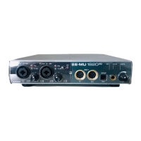
Overview of the AudioDock unit and its features.
Details the front panel connections and controls on the AudioDock.
Details the microphone and line preamplifier section.
Explains the MIDI ports on the AudioDock front panel.
Describes the S/PDIF optical output on the front panel.
Details the headphone output and its volume control.
Explains the LED indicators on the AudioDock front panel.
Describes the MIDI activity indicators.
Explains the LED indicators for clock and sample rate.
Details the function of the Clock Source LEDs.
Explains the Sample Rate LEDs.
Details the connections on the AudioDock rear panel.
Describes the analog line level inputs.
Explains the turntable inputs and ground lug.
Describes the analog line level outputs.
Details the analog outputs for computer speakers.
Explains the second set of MIDI ports.
Describes the EDI connector on the PCI card.
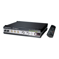
Overview of the Sync Daughter Card.
Describes the connections on the Sync Daughter Card.
Introduction to the PatchMix DSP mixer application.
How to open the PatchMix DSP mixer window.
Provides a visual overview of the PatchMix DSP mixer interface.
Details the four main sections of the mixer window.
Explains the difference between pre-fader and post-fader aux sends.
How to access PatchMix DSP from the Windows taskbar.
Describes the functions of the toolbar buttons in PatchMix DSP.
Manages the state of the mixer setup, including saving and loading.
Steps to create a new mixer session with templates.
How to load previously saved mixer sessions.
Instructions for saving the current mixer setup.
Configuration options for system, MIDI, and I/O.
Details the system settings like clock source and sample rate.
How to synchronize with external clock sources.
Configuration for MIDI input/output and sync card.
Adjusts input/output levels and formats.
Describes the components and types of input mixer strips.
Explains the types of inputs for mixer strips.
Steps to add and configure new mixer strips.
Information on multichannel audio file support.
How to configure playback for surround sound.
Details the insert section for effects and routing.
How to add, manage, and use inserts.
Describes the context menu for inserts.
Steps to insert a send for routing audio.
Steps to insert a send/return for external processing.
How to route signals to external gear.
Using ASIO for zero-latency monitoring.
Using meters to monitor signal levels.
Guide to setting optimal input levels using meters.
Tips for achieving optimal recording levels.
Using the Trim Pot insert for gain adjustment.
Using the test tone generator for troubleshooting.
How to delete, bypass, and solo inserts.
Details the auxiliary sends and their functions.
Diagram illustrating post-fader aux sends.
Alternative ways to use auxiliary sends.
Explains the behavior of pre and post-fader aux sends.
Describes controls for strip level, pan, solo, and mute.
Overview of the main section controls and displays.
Explains the TV screen display and its functions.
Controls for selecting and programming effects.
Displays input routing information.
Displays output routing information.
Assigning effects to auxiliary buses.
Diagram illustrating post-fader aux sends.
Shows current sync and sample rate status.
Describes controls for the main stereo output.
Applying effects to the main stereo signal.
Controls the main stereo output level.
Displays the digital level at the mixer output.
Adjusts the monitor output level.
Adjusts the relative volume of stereo monitor outputs.
Cuts off the monitor output sound.
Introduces the DSP effects included with PatchMix DSP.
Describes how to access and use the effects palette.
How to save multiple effects as a single chain.
Utilities for organizing effects presets.
How to share presets with others.
Details how to edit effect parameters.
Managing and using user-created effect presets.
Information on core effects and preset file management.
Lists all available core DSP effects.
Explains how effects consume DSP resources.
Detailed descriptions of individual core effects.
Description of the 1-Band Parametric Equalizer effect.
Description of the 1-Band Shelving Equalizer effect.
Description of the 3-Band Equalizer effect.
Description of the 4-Band Equalizer effect.
Description of the Auto-Wah effect.
Description of the Chorus effect.
Description of the Compressor effect.
Explains the basic controls of the compressor.
Description of the Distortion effect.
Description of the Flanger effect.
Description of the Frequency Shifter effect.
Description of the Leveling Amp effect.
Description of the Lite Reverb effect.
Description of mono delay effects.
Description of the Phase Shifter effect.
Description of the Rotary speaker simulation effect.
Description of the Speaker Simulator effect.
Description of stereo delay effects.
Description of the Stereo Reverb effect.
Description of the Vocal Morpher effect.
Using E-MU PowerFX with VST hosts.
Recording parameter changes for PowerFX.
Understanding resource limitations for PowerFX.
Advice for rendering audio with PowerFX.
Specific tips for using Freeze Mode in Cubase LE.
Troubleshooting stuttering issues with specific software.
Using the E-Wire VST bridge for routing.
Compensating for audio transfer delays.
Setting the parameter for E-Delay Compensator.
Using E-Delay Compensator on grouped tracks.
Explains changes in mixer functionality at higher sample rates.
Details I/O configurations at 88.2k/96k sample rates.
Table showing I/O at 88.2k/96kHz.
Details I/O for 1212M at 88.2k/96k sample rates.
Table showing I/O for 1212M at 88.2k/96kHz.
Details I/O configurations at 176.4k/192k sample rates.
Table showing I/O at 176.4k/192kHz.
Details I/O for 1212M at 176.4k/192k sample rates.
Table showing I/O for 1212M at 176.4k/192kHz.
Explains WDM driver behavior with PatchMix sample rates.
Additional information about the Sync Daughter Card.
How the Sync Daughter Card converts SMPTE to MTC.
Lists the SMPTE conversion and output features.
Configuring SMPTE settings in PatchMix DSP.
Explains different modes for SMPTE operation.
Details the flywheel modes for handling data dropouts.
Descriptions of the different flywheel modes.
How to record SMPTE time code onto an audio track.
Provides background information on SMPTE time code.
Lists the different types of SMPTE time code.
Explains the advantages of using SMPTE sync.
How to record SMPTE time code.
Tips for preventing issues with SMPTE time code.
How to copy SMPTE time code.
Additional advice for using SMPTE.
Diagram and explanation of a typical SMPTE connection.
Explanation of MIDI Time Code.
How to synchronize devices using word clock.
How to synchronize digital audio devices.
General helpful information for users.
Information on using an adapter cable.
Explains the difference and use of balanced/unbalanced cables.
Advice on using quality digital cables.
Importance of proper grounding for noise reduction.
Information about phantom power for microphones.
Adjusting Windows settings for better performance.
| Type | Audio interface |
|---|---|
| Manufacturer | Creative |
| Audio Interface Type | PCI |
| Number of Inputs | 8 |
| Sample Rate | 192 kHz |
| Bit Depth | 24-bit |
| Frequency Response | 20 Hz - 20 kHz |
| MIDI Interface | Yes |
| Interface | PCI |
| Compatibility | Windows |
| Model | E-MU 1820M |
| Digital Audio Interface | ADAT, S/PDIF |
| Analog Audio Interface | 1/4" TRS |
| Inputs | S/PDIF, ADAT |
| Outputs | S/PDIF, ADAT |