Do you have a question about the Crest Audio FCV220 and is the answer not in the manual?
Carefully open carton, check for damage, notify shipper, save packing material.
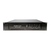
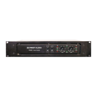
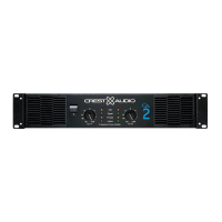
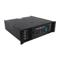
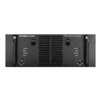
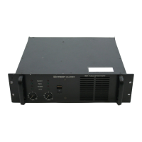
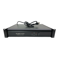
Mount in 19" rack; uses forced-air cooling and intelligent fan for optimal temperature.
Verify AC voltage, use quality cables, set mode switch correctly for intended application.
Input connections via barrier strip, supports balanced/unbalanced, uses octal accessory sockets.
Connect speakers/lines via barrier strip; details direct and distributed line outputs.
Details current demand, circuit sizes, and voltage conversion for amplifier power connection.
Both channels operate independently with input attenuators controlling individual levels.
Dual channel, single input mode; both channels driven by Channel A input.
Bridges channels for high-power monaural output; describes mode switch and connections.
Critical precautions for bridged mode: never ground speaker cable sides; both outputs are 'hot'.
Explains driving multiple speakers with transformers and the concept of constant voltage systems.
Provides tables to determine optimal copper wire gauge for speaker and distributed line cables.
Discusses amplifier heat output, system cooling needs, and ambient temperature effects.
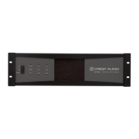
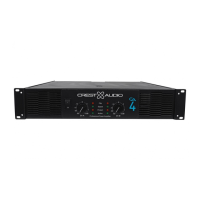
Front panel combination AC switch and magnetic circuit breaker for power control.
Back panel controls adjusting amplifier channel gain; set fully clockwise for headroom.
Rear panel switch to select stereo, parallel, or bridged mono operating modes.
Jumper on output barrier strip to isolate signal ground from chassis ground, preventing loops.
Red LED indicates clipping onset. Flashing means peaking; steady glow means hard-clipping.
Bi-color LEDs: green for normal operation, red for output relay open (protection).
Protects against heat; fan maintains range, heat sinks trigger relay, transformer sensor cuts AC.
Limits output current on short circuits; thermally protects channel by disconnecting load.
Detects DC voltage at output, immediately opens relay to prevent loudspeaker damage.
High-pass filter prevents saturation; DC protection activates on excessive subsonic energy.
Outputs disconnected ~3s at power up; immediate disconnect on power removal prevents thumps.
| Brand | Crest Audio |
|---|---|
| Model | FCV220 |
| Category | Amplifier |
| Language | English |