quickstart guide
CEN-CI3-3
www.crestron.com
888.273.7876 201.767.3400
Specifications subject to
change without notice.
CEN-CI3-3
3-Series™ Card Interface - 3 Slot
QUICKSTART DOC. 7309A (2032664) 06.12
1
3
Dimensions
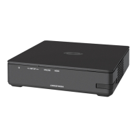
The CEN-CI3-3 is designed to be placed on a shelf or rack mounted using the
included rack ears.
1
Install the CEN-CI3-3
2
Establish Communication
Ear Attachment for Rack Mounting
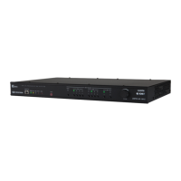
CEN-CI3-3 Plug-in Card Installation
NOTE: Use the Device Discovery Tool in Crestron Toolbox to detect all
Ethernet devices on the network and their IP configuration. The tool is
available in Toolbox version 1.1.5.143 or later.
The CEN-CI3-3 connects to PC via Ehernet:
2. Confirm Ethernet connection between card interface and PC. If connecting
through a hub or router, use CAT5 straight through cables with 8-pin RJ-45
connectors. Alternatively, use a CAT5 crossover cable to connect the two
LAN ports directly without using a hub or router (via static IP and a power
injector, if no other power is supplied).
NOTE: Some PCs may not require a crossover cable. Check with PC
manufacturer.
Ethernet Communication
1. Enter the IP address, IP mask and default router of the card interface via
Crestron Toolbox (Functions | Ethernet Addressing); otherwise enable
DHCP.
3. Use the Address Book in Crestron Toolbox to create an entry for the
CEN-CI3-3 with the CEN-CI3-3’s TCP/IP parameters.
Use Crestron Toolbox™ for communicating with the CEN-CI3-3; refer to the
Crestron Toolbox help file for details.
PC Running
Crestron Toolbox
LAN
CEN-CI3-3
There is a single method of communication: TCP/IP communication.
4. Display the “System Info” window (click the icon) and select the card
interface entry.
CEN-CI3-3 Overall Dimensions (Front, Top and Side Views)
CAUTION: The CEN-CI3-3 should be used in a well ventilated area. The venting
holes on the top and sides should not be obstructed under any circumstances.
!
* Remove blank faceplate to insert plug-in card.
To install the ears:
1. There are screws that secure each side of the CEN-CI3-3 top cover. Using a
#1 or #2 Phillips screwdriver, remove the three screws closest to the front
panel from one side of the unit. Refer to the illustration below for a detailed view.
2. Position a rack ear so that its mounting holes align with the holes vacated by
the screws in step 1.
3. Secure the ear to the unit with three screws from step 1, as shown in the
following illustration.
4. Repeat procedure (steps 1 through 3) to attach the remaining ear to the
opposite side.
NOTE: The CONTROL SUBNET ports work with LANs as well as with control
subnet networks. The CONTROL SUBNET OUT port can be used for daisy
chaining.
Blank Faceplates *
10.06 in
(256 mm)
1.70 in
(44 mm)
19.00 in
(483 mm)
9.78 in
(249 mm)
17.29 in
(440 mm)