quickstart guide
CEN-CI3-3
www.crestron.com
888.273.7876 201.767.3400
Specifications subject to
change without notice.
CEN-CI3-3
3-Series™ Card Interface - 3 Slot
QUICKSTART DOC. 7309A (2032664) 06.12
2
4
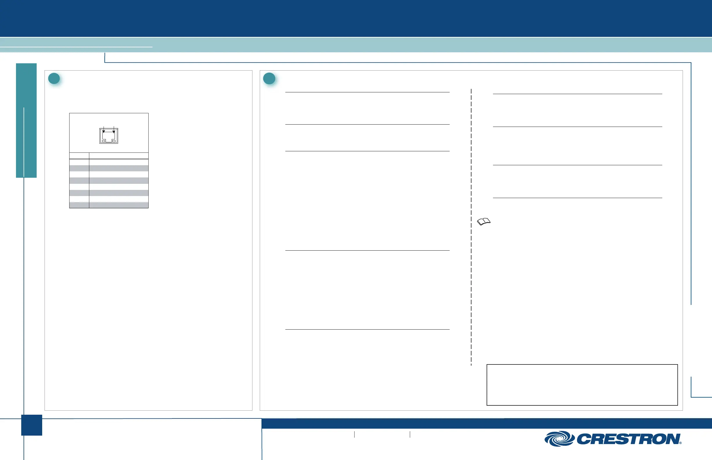
Pinout Reference
In addition to its front panel COMPUTER port, the CEN-CI3-3 has two CONTROL
SUBNET ports.
5
Specifications
The specific patents that cover Crestron products are listed at patents.crestron.com.
Crestron, the Crestron logo, 3-Series and Crestron Toolbox are either trademarks or registered
trademarks of Crestron Electronics, Inc. in the United States and/or other countries. Other trademarks
and trade names may be used in this document to refer to either the entities claiming the marks and
names or their products. Crestron disclaims any proprietary interest in the marks and names of others.
©2012 Crestron Electronics, Inc.
Communications
Ethernet: 10/100/1000 Mbps, auto-switching, auto-negotiating, auto-discovery,
full/half duplex, DHCP
USB: For computer console
Ethernet Switch
Provides (1) rear panel uplink port, (3) internal ports for the card slots,
and (1) rear panel port
Connectors & Card Slots
S1 – S3: (3) 3-Series™ control card expansion slots
CONTROL SUBNET IN: (1) 8-wire RJ-45 jack
10/100/1000BASE-T Ethernet uplink port
CONTROL SUBNET OUT: (1) 8-wire RJ-45 jack
10/100/1000BASE-T Ethernet port
24VDC 2A MAX: (1) 2.1 mm barrel DC power jack, 24 Volt DC power input,
power pack included
G: (1) 6-32 screw, chassis ground lug
COMPUTER (front): (1) USB Type B female
USB 2.0 computer console port (6 ft cable included)
For setup only
Controls & Indicators
PWR: (1) Green LED, indicates operating power supplied from power pack
MSG: (1) Red LED, indicates unit has generated an error message
RESET: (1) Recessed push button for hardware reset
SETUP: (1) Recessed push button with red LED for Ethernet auto-discovery
SLOT 1 – 3: (3) Green LEDs, indicate control cards are inserted in the
corresponding slots
CONTROL SUBNET IN (rear): (2) Bi-color green/amber LEDs, left LED indicates
Ethernet connection speed (off for 10 Mbps, green for 100 Mbps, amber for 1000
Mbps), right LED indicates Ethernet activity
CONTROL SUBNET OUT (rear): (2) Bi-color green/amber LEDs, left LED
indicates Ethernet connection speed (off for 10 Mbps, green for 100 Mbps,
amber for 1000 Mbps), right LED indicates Ethernet activity
Power Requirements
Power Pack: 2.0 Amps @ 24 Volts DC
100-240 Volts AC, 50/60 Hz power pack included
Environmental
Temperature: 41° to 113°F (5° to 45°C)
Humidity: 10% to 90% RH (non-condensing)
Heat Dissipation: 6 BTU/Hr without cards*
Enclosure
Chassis: Metal, black finish, vented top and sides
Faceplate: Metal, black finish, polycarbonate label overlay
Mounting: Freestanding or 1U 19-inch rack-mountable (adhesive feet and rack
ears included)
Dimensions
Height: 1.70 in (44 mm) without feet
Width: 17.29 in (440 mm), 19.00 in (483 mm) with rack ears
Depth: 10.06 in (256 mm)
Weight
5.0 lb (2.3 kg) without cards
* Refer to individual control card Installation Guides for additional specifications. They are
available from the Crestron
®
Web site (www.crestron.com/manuals).
CONTROL SUBNET
PIN DESCRIPTION
1
2
3
4
5
6
7
8
BI _ DA +
BI _ DA -
BI _ DB +
BI _ DD -
BI _ DD +
BI _ DB -
BI _ DC +
BI _ DC -
Pin 8 Pin 1

 Loading...