EasyManuals Logo

Crestron CGEIB-IP User Manual

Crestron CGEIB-IP
41 pages
To Next Page IconTo Next Page
To Previous Page IconTo Previous Page
Page #11 background imageLoading...
Page #11 background image
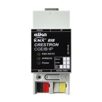
Crestron CGEIB-IP KNX Control Interface
Operations & Installation Guide DOC. 0009 KNX/EIB Control Interface: Crestron CGEIB-IP
3
Connectors, Controls & Indicators
#
CONNECTORS,
CONTROLS &
INDICATORS
DESCRIPTION
1
KNX/RX/TX LED
Color: red/green
Red upon KNX data received, green upon
KNX data transmitted.
2
IP/RS232 LED
Color: red
Red with RS232 connected (DTR=High),
green with IP connected.
3
Power LED
Color: blue
Blue if operating voltage is applied.
4
RS232 Connector
DB9 female, bidirectional RS232 port
5
RJ-45 Connector
RJ-45 Socket
6
KNX BUS Connector
Wago connector that connects the CGEIB-IP
with the KNX bus.
7
Power Connector
Wago connector used to power the CGEIB-
IP. The CGEIB-IP should be powered with
24V AC/DC
8
KNX Programming-LED
Color: red
Red when CGEIB-IP is in ETS programming
mode.
9
Programming button
Press to set the unit in ETS programming
mode.

Questions and Answers:

Question and Answer IconNeed help?

Do you have a question about the Crestron CGEIB-IP and is the answer not in the manual?

Crestron CGEIB-IP Specifications

General IconGeneral
BrandCrestron
ModelCGEIB-IP
CategoryControl Unit
LanguageEnglish

Related product manuals