Temperature & Humidity Sensors Crestron CHV-RTS & CHV-RTHS
4 • Temperature/Humidity Sensors: CHV-RTS/CHV-RTHS Installation Guide – DOC. 8189D
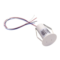
Setup
Installation
NOTE: Ensure the installation location is not close to a heat or humidity
source and is away from direct sunlight, skylights, and windows. When
mounting the sensor outdoors, do not place in direct sunlight and do not
place where the sensor is directly exposed to precipitation. Sensors are
suitable for mounting in dry or damp locations as defined by the National
Electrical Code.
Complete the following procedure to install the CHV-RTS or
CHV-RTHS.
1. Locate an area on the wall that is free of miscellaneous wiring and
studs.
2. Make a small hole near the center of the desired area to verify the
location is suitable.
3. Drill or cut a 1 inch (25 mm) diameter circular hole in the wall at
the desired position.
4. Route the wires from the thermostat to the sensor. For thermostat
connection details, refer to the Crestron CHV-TSTAT and
CHV-THSTAT Thermostats Operations and Installation Guide
(Doc. 8163), the CHV-TSTATEX Thermostat Operations and
Installation Guide (Doc. 6989), or the CHV-TSTATEX-FCU
Thermostat Operations and Installation Guide (Doc. 7206) at
www.crestron.com/manuals.
NOTE: Crestron strongly recommends low-capacitance twisted
pair wire such as CAT3 (up to 250 feet (76 meters)) or CAT5 (up
to 500 feet (152 meters)) network cable when using remote
sensors. Other cable types are satisfactory, provided the total
capacitance is less than 7000 pF. Maximum distance from sensor
to thermostat is 500 feet (152 meters).