CLW-DIM1, DIMS1, & SLVD1(W/A/B)
Appendix: Wiring Diagrams
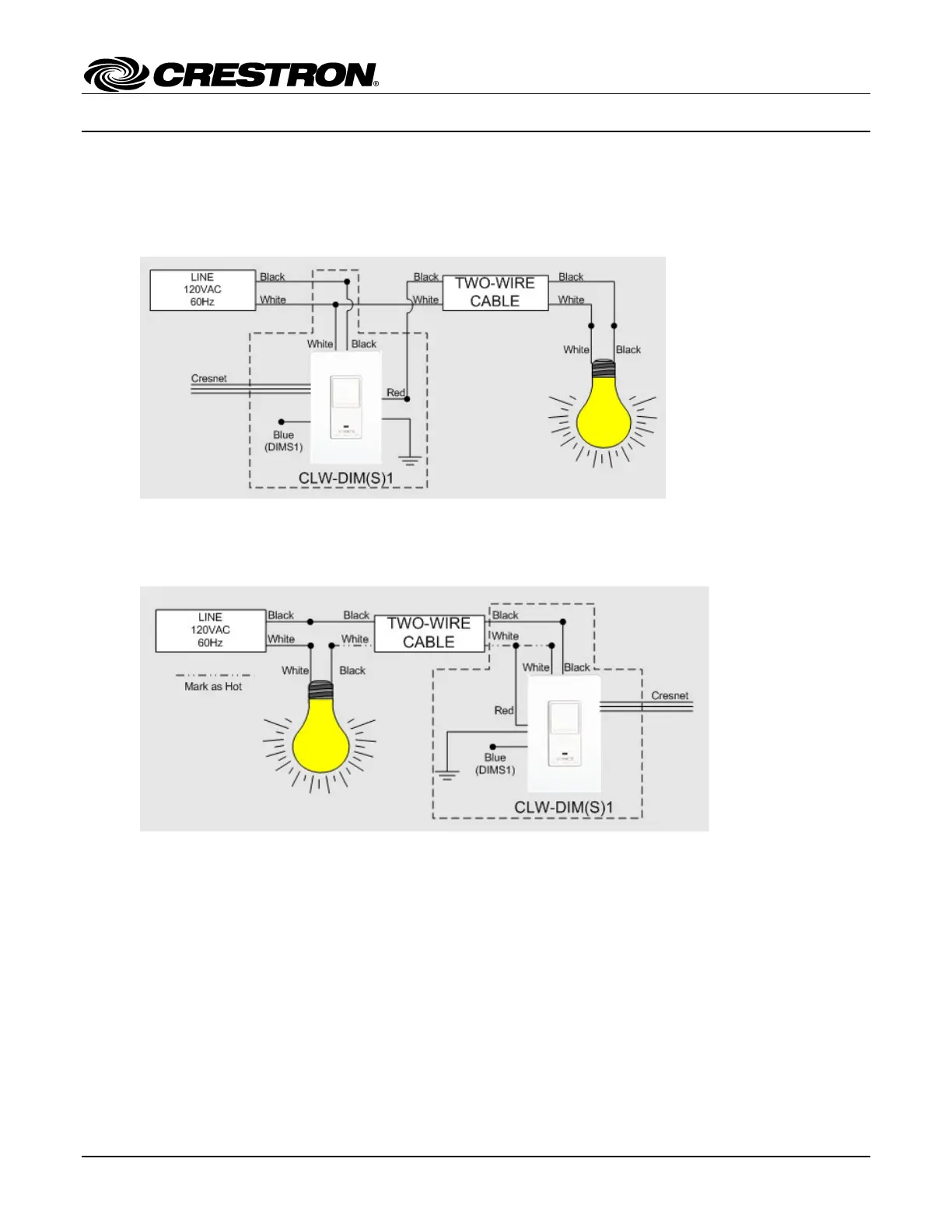
Following are wiring diagrams for circuits that may be found when installing a dimmer:
Stand-Alone Installations
Figure 1: Wiring a CLW-DIM(S)1
• Since a -DIMS1 is installed without a slave, the blue lead of the -DIMS1 must be capped.
If a neutral is not present in the wallbox, the wiring shown in the following diagram can be used.
Figure 2: Alternative Wiring of -DIM1 and -DIMS1 Where Neutral is Not Present (Load-Fed Switch Loop)
In the above configuration:
• The white wire from the -DIMS1 to the load is coded HOT.
• Since a -DIMS1 is installed without a slave, the blue lead of the -DIMS1 must be capped.
• The minimum load requirement is 100W.
• Bulb noise may be present even when the load is off.
• Circuits with small magnetic low-voltage loads may not work.
8 • Stand Alone Wall Box Dimmer: CLW-DIM1, DIMS1, & SLVD Installation Guide – DOC. 6250A
 Loading...