Do you have a question about the Crouzet MILLENIUM II+ Series and is the answer not in the manual?
Introduction to the MILLENIUM II series, its fields of use, and key features.
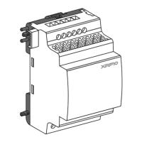
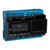
Lists and details the available part numbers for the MILLENIUM II series products.
Details specifications, inrush current, consumption, and immunity for different power supplies.
Describes input voltage, frequency, impedance, and levels for AC and DC inputs.
Details specifications for relay outputs, including voltage, current, load, and durability.
Details specifications for transistor outputs, including voltage, current, and loads.
Provides general details on programming, capacity, backup, and LCD display features.
Details environmental conditions (temperature, humidity) and mechanical resistance (vibration, shock).
Covers safety classifications, electrical standards, and product certifications (CE, UL).
Explains DIN rail and panel mounting procedures for the modules.
Provides guidance on connecting wires to screw terminals using ferrules.
Important notes on installation environment, spacing, and ventilation for optimal performance.
General connection advice, conductor size, stripping, and tightening torque for terminals.
Instructions for correctly connecting AC and DC power supplies to the module terminals.
Illustrates the wiring diagrams for AC and DC input configurations.
Illustrates the wiring diagrams for relay and transistor output connections.
Explains safety symbols and provides warnings for material damage and dangerous situations.
Outlines user responsibilities, system suitability, modification prohibition, and compliance checks.
| Brand | Crouzet |
|---|---|
| Model | MILLENIUM II+ Series |
| Category | Controller |
| Language | English |