Power Base-3 & 1400CSL Amplifier Service Manual
14
TEST 6: VOLTAGE GAIN
Spec 26dB Gain: ±3%.
Spec 0.775V Sensitivity: ±6%.
Spec 1.4V Sensitivity: +12%/–6%.
Initial Conditions: Controls per standard.
Procedure: No load connected. Inject a 0.775 VAC 1
kHz sine wave with the Sensitivity Switch in the 26 dB
position. Measure 15.5 VAC ±0.5 VAC at the amplifier
output. Inject a 0.775 VAC 1 kHz sine wave with the
Sensitivity Switch in the 0.775V position. Measure 65.7
VAC ±3.9 VAC at the amplifier output. Inject a 1.4 VAC
1 kHz sine wave with the Sensitivity Switch in the 1.4V
position. Measure 65.7 VAC +7.8/-3.9 VAC at the
amplifier output. Return the Sensitivity Switch to the 26
dB position.
TEST 7: PHASE RESPONSE
Spec: ±10° from 10 Hz to 20 kHz at 1 Watt.
Initial Conditions: Controls per standard, 8 ohm load on
each channel.
Procedure: Inject a 1 kHz sine wave and adjust for 1
Watt output (2.8 VAC). Check input and output signals
against each other, input and output signals must be
within 10° of each other.
TEST 8: LEVEL CONTROLS
Spec: Level controlled by level controls.
Initial Conditions: Controls per standard.
Procedure: No Load. Inject a 1 kHz sine wave. With
level controls fully clockwise you should see full gain.
As controls are rotated counterclockwise, observe
similar gain reduction in each channel. When com-
plete, return level controls to fully clockwise position.
TEST 9: CURRENT LIMIT
Spec: Current Limit at 38 ±3 Amps
Initial Conditions: Controls per standard.
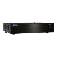
Procedure: Load each channel to 1 Ohm. Inject a 1 kHz
differentiated (or 10% duty cycle) square wave and
increase output level until current limit occurs. Current
limit should occur at 38 ±3 Amps (38 Vpk) with output
device Vce less than 40 Vpk. Observe clean (no
oscillations) current clipping.
Electrical Checkout Procedures
TEST 10: SLEW RATE & 10 KHZ SQUARE WAVE
Spec: >17V/µS.
Initial Conditions: Controls per standard.
Procedure: Load each channel to 8 ohms. Inject a 10
kHz square wave to obtain 65 volts peak-to-peak at
each output. Observe the slope of the square wave. It
should typically measure 17 to 25 V/µS. Also, the
square wave must not include overshoot, ringing, or
any type of oscillation.
TEST 11: CROSSTALK
Spec: -60dB at 20 kHz.
Initial Conditions: Controls per standard. Terminate
input of channel not driven with 600 ohms.
Procedure: 8 ohm load on each channel. Inject a 20 kHz
sine wave into the Channel 1 input and increase output
level to 62 VAC. Measure less than 62 mVAC at the
output of Channel 2. Inject a 20 kHz sine wave into the
Channel 2 input and increase output level to 62 VAC.
Measure less than 62 mVAC at the output of Channel
1.
TEST 12: OUTPUT POWER
Spec at 8 Ohm Stereo: 540W at 0.1% THD.
Spec at 4 Ohm Stereo: 760W at 0.1% THD.
International 8 Ohm Stereo:International 8 Ohm Stereo:
International 8 Ohm Stereo:International 8 Ohm Stereo:
International 8 Ohm Stereo: 510W at 0.1% THD.
International 4 Ohm Stereo:International 4 Ohm Stereo:
International 4 Ohm Stereo:International 4 Ohm Stereo:
International 4 Ohm Stereo: 680W at 0.1% THD.
Initial Conditions: Controls per standard.
Procedure: Load each channel to 8 ohms. Inject a 1 kHz
sine wave and measure at least 65.7 VAC at the output
of each channel. Load each channel to 4 ohms. Inject
a 1 kHz sine wave and measure at least 55.1 VAC. All
power measurements must be at less than 0.1% THD.
TEST 13: REACTIVE LOADS
Spec: No oscillations. Safe with all types of loads.
Initial Conditions: Controls per standard.
Procedure Capacitive: Load each channel to 8 ohms in
parallel with 2 µF. Inject a 20 kHz sine wave with 55
VAC output for 10 seconds.
Procedure Inductive: Load each channel to 8 ohms in
parallel with 159 µHenries. Inject a 1 kHz sine wave
with 35.8 VAC output for 10 seconds.
Procedure Torture: Load each channel with the primary
(red and black leads) of a DC-300A transformer (D
5781-6). Inject a 10 Hz sine wave at sufficient output
level to cause 3 to 5 flyback pulses, for 10 seconds.
Procedure Short: Inject a 60 Hz sine wave at 5 VAC
minimum output. After establishing signal, short the
output for 10 seconds.
In
Out
.047 uF
1K Ohm
Differenciator Circuit