Do you have a question about the Crown 1200 and is the answer not in the manual?
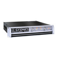
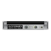
Describes the manual's applicability to MT-1200/1201 amplifier models.
Outlines procedures for warranty claims, factory service, and authorized centers.
Explains Crown's part numbering systems and how to order replacement parts.
Details shipping procedures, payment terms, and return policies.
Details output power ratings, frequency response, distortion, and noise specs.
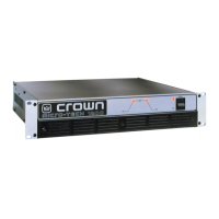
Covers impedance, protection systems, connectors, construction, and dimensions.
Details jumper settings and fuse changes for different voltage configurations.
Introduces amplifier theory, highlights features, and explains initial signal processing.
Describes signal amplification, translation, and the grounded bridge topology.
Details output stage operation and the ODEP protection system.
Covers initial conditions, DC offset, bias, ODEP, AC power, and CMR tests.
Covers gain, phase, slew rate, crosstalk, output power, and protection tests.
Covers IMD, turn-on/off transients, reactive loads, and clipping tests.
Details returning controls to factory settings after testing.
Lists general hardware, chassis parts, and power supply components.
Lists components specific to the output stage assembly.
Lists parts for the front panel, back panel, and main chassis assemblies.
Provides an overview of module revisions, output, main, fuse, and display modules.
Explains the representative nature and usage of provided amplifier schematics.
| Total Harmonic Distortion | <0.05% |
|---|---|
| Channels | 2 |
| Dimensions | 19" x 3.5" |
| Input Impedance | 20 kOhms balanced, 10 kOhms unbalanced |
| Damping Factor | >500 |
| Cooling | Forced air, front-to-back |