Do you have a question about the Crown Micro-Tech 1201 and is the answer not in the manual?
Summary of Crown International's worldwide warranty terms and conditions for new products, excluding accidental damage.
Summary of Crown International's North America warranty terms and conditions for new products, excluding accidental damage.
Instructions for unpacking and inspecting the new amplifier for transit damage and retaining packing materials.
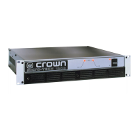
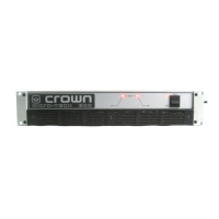
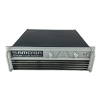
Overview of key features, patented technologies, and benefits of the Micro-Tech amplifiers.
Description of the front panel filter grille and its dust filter for maintaining cooling efficiency.
Explanation of front panel ODEP and enable indicator lights, their meanings, and operational status.
Details on the front panel power switch function and AC power cord connection requirements.
Information on the back panel switch for selecting operating modes: Stereo, Bridge-Mono, Parallel-Mono.
Location and function of the reset switches for circuit breakers on the MT-2400 model.
How to access and adjust the input sensitivity switch located behind the cover plate.
Description of back panel level controls, phone jack inputs, and ground lift switch function.
Details on output binding posts and connection methods for phone jack inputs.
Recommendations for rack mounting or stacking Micro-Tech amplifiers for proper support and stability.
Essential tips for maintaining proper amplifier cooling and preventing overheating through airflow management.
Overview of connecting the amplifier in a sound system, outlining modes and critical precautions.
Step-by-step instructions for wiring the amplifier in Stereo mode for normal two-channel operation.
Instructions for wiring the amplifier in Bridge-Mono mode to drive loads requiring higher voltage output.
Instructions for wiring the amplifier in Parallel-Mono mode to drive loads requiring higher current output.
Details on connecting balanced and unbalanced input signals using various connector types and sources.
Guidelines for connecting loudspeakers, including wire gauge selection and connector use for optimal performance.
How to use fuses for speaker protection against thermal damage and transient voltages.
Information on power cord types, voltage, and frequency requirements for various regions and models.
Essential safety and operational precautions to ensure optimal performance and safety during use.
Detailed explanation of the front panel enable and ODEP indicators and their operational meanings.
Covers ODEP, Ultrasonic/RF, Drive, Transformer Thermal, and Fuse/Circuit Breaker protections.
Discussion of advancements like computer simulation, output stages, and heat sinks in amplifier design.
Explains stereo, bridge-mono, and parallel-mono operation, including circuit paths and protection mechanisms.
Details frequency response, signal-to-noise, THD, IMD, damping factor, slew rate, and voltage gain.
Lists minimum guaranteed output power for various modes and loads across all models.
Information on safe load impedance ranges and required AC mains power for operation.
Detailed minimum power output values for MT-600 in various modes and loads.
Explains measurement standards (1kHz, 20Hz-20kHz, THD+N) for power specifications.
Detailed minimum power output values for MT-1200 in various modes and loads.
Detailed minimum power output values for MT-2400 in various modes and loads.
Details MT-600 max power for single cycle tone bursts at various frequencies.
Details MT-600 max power for 40ms tone bursts at various frequencies.
Details max power for MT-1200 using single cycle and 40ms tone bursts.
Details max power for MT-2400 using single cycle and 40ms tone bursts.
Explains equations for calculating AC mains power draw and thermal dissipation based on duty cycle.
Table showing AC power, current, and thermal dissipation for MT-600 at various duty cycles.
Table showing AC power, current, and thermal dissipation for MT-1200 at various duty cycles.
Table showing AC power, current, and thermal dissipation for MT-2400 at various duty cycles.
Information on optional replacement fan blades for special cooling requirements.
Details on accessory panels for XLR and barrier strip inputs, and their installation.
How to obtain service for Crown products globally through authorized service centers.
Information on obtaining service in North America via authorized service centers or the factory.
| Channels | 2 |
|---|---|
| 8 Ohm Stereo | 275W |
| Signal to Noise Ratio | > 100 dB |
| THD | < 0.05% |
| Input Sensitivity | 1.4V |
| Frequency Response | 20 Hz - 20 kHz |
| Input Impedance | 20 kOhm balanced, 10 kOhm unbalanced |
| Cooling | Fan-cooled |
| Dimensions | 19" x 3.5" x 12.25" (483 x 89 x 311 mm) |